Opel Frontera UBS. Manual - part 1066


  Index      Opel     Opel Frontera UBS - service repair manual 1998-2002 year


Search            


Content   ..  1064  1065  1066  1067   ..


Opel Frontera UBS. Manual - part 1066


4D1–26 TRANSFER CASE (STANDARD TYPE)

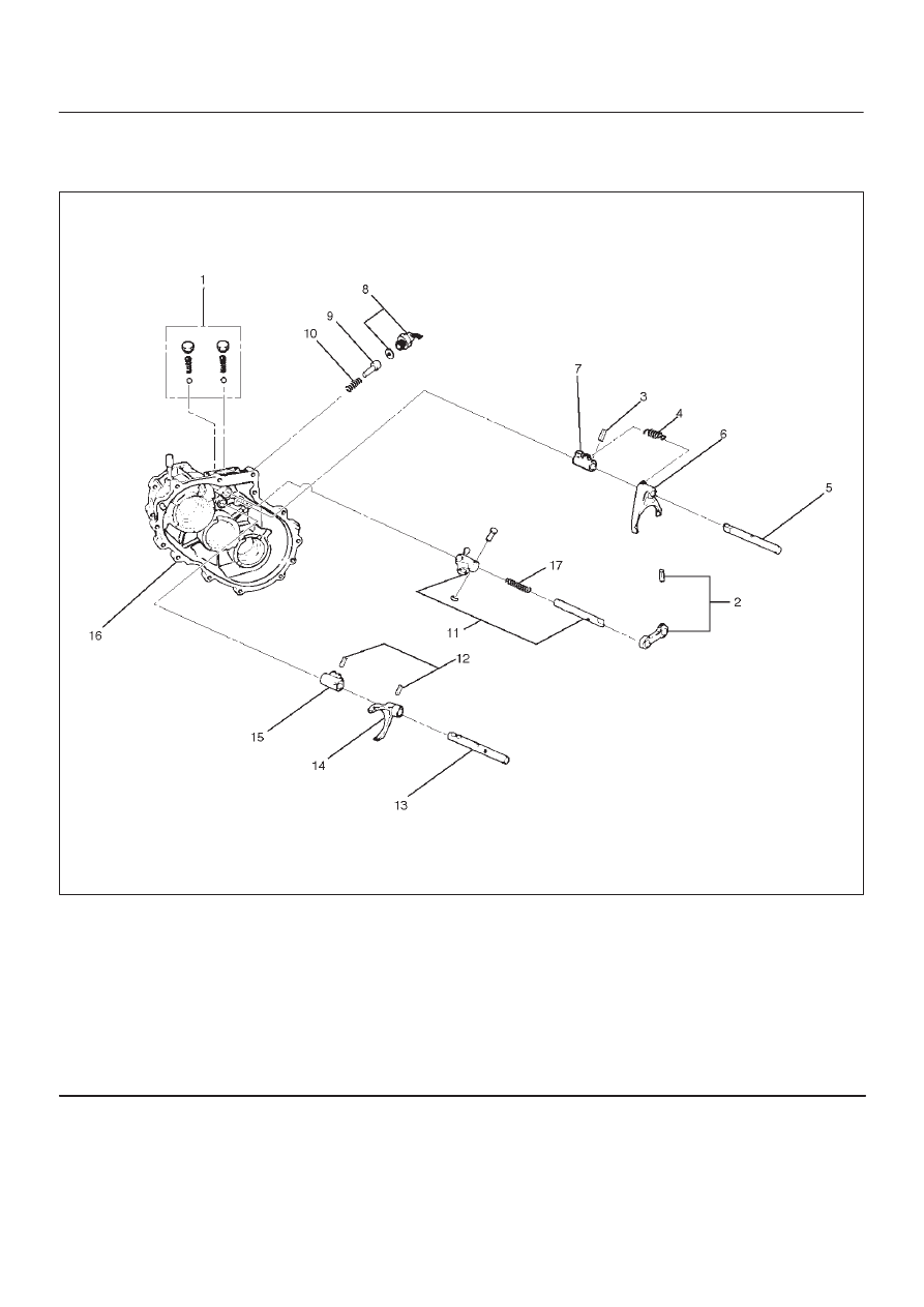
Detent, Shift Arm, and Interlock Pin

Disassembled View

262RW074

Legend

(1) Detent Ball, Spring and Plug
(2) Spring Pin and Bridge
(3) Spring Pin
(4) Spring
(5) 2WD–4WD Shift Rod
(6) Shift Arm
(7) Shift Block
(8) 4WD Indicator Switch

(9) Interlock Pin

(10) Spring

(11) Select Rod Assembly

(12) Spring Pin
(13) High–Low Shift Rod
(14) Shift Arm
(15) Shift Block
(16) Transfer Case
(17) Spring (Except Shift On The Fly Model)

Disassembly

1. Remove the detent ball, spring and plug (1).

TRANSFER CASE (STANDARD TYPE)

4D1–27

2. Use a spring pin remover to remove the spring pin (2)

from the bridge (2).

262RW011

3. Remove the spring (4).
4. Engage the 2WD–4WD sleeve with the front output

gear. Remove the spring pin (3) from the block (7).
Remove the 2WD–4WD shift rod (5).

262RW022

5. Remove the shift arm (6).
6. Remove the shift block (7).
7. Remove the 4WD indicator switch (8).

8. Use a magnetic tool to remove the interlock pin (9)

and spring (10) from the transfer case (16).

262RS005

9. Remove the select rod assembly (11).

10. Use a spring pin remover to remove the shift arm

spring pins (12) from the shift arm (14) and shift block
(15). Remove the high–low shift rod (13) from the
transfer case (16).

262RS006

11. Remove the shift arm (14).

12. Remove the shift block (15) from the transfer case

(16).

4D1–28 TRANSFER CASE (STANDARD TYPE)

Inspection and Repair

Refer to “TRANSFER CASE ASSEMBLY” in this section
for inspection and repair.

Reassembly

1. Place the shift block (15) in the transfer case (16).
2. Set the shift arm (14) on the High–Low sleeve.
3. Push the High–Low shift rod (13) through the shift

arm (14) and block (14).

4. Engage the High–Low sleeve with the 4H (1) side.
5. Install the spring pins (12) to the shift block (15) and

shift arm (14).

262RW012

6. Install the select rod assembly (11), joining its lever to

the shift block groove.

7. Engage the High–Low sleeve with the 4H side and

install the the interlock pin (9) and spring (10) in the
proper direction.

8. Place the 2WD–4WD shift block (7) in the transfer

case (16).

9. Set the 2WD–4WD shift arm (6) on the 2WD–4WD

sleeve.

10. Push the 2WD–4WD shift rod (5)  through the

2WD–4WD shift arm (6) and 2WD–4WD shift block
(7).

11. Install the 2WD–4WD shift rod (5) with the interlock

pin pushed in.

262RW035

Legend

(18) 2WD–4WD
(19) 4H Side
(20) Interlock pin
(21) 2WD
(22) 4WD
(23) Rod: 2–4
(24) Rod: H–L
(25) 4H
(26) 4L
(27) 4

×

2

(28) 4

×

4

12. Install the 4WD indicator switch and gasket (8).

Tighten to the specified torque.

Torque: 39 N·m (4.0kg·m/29 lb ft)

13. Install the spring (4).

TRANSFER CASE (STANDARD TYPE)

4D1–29

14. Engage the 2WD–4WD sleeve with the 4WD side and

install the spring pin (3).

262RW022

15. Install the spring pin and bridge (2).
16. Install the detent ball, spring and plug and tighten the

plug (1) to the specified torque.

Torque: 25 N·m (2.5kg·m/18 lb ft)


Content   ..  1064  1065  1066  1067   ..