Opel Frontera UBS. Manual - part 1064


  Index      Opel     Opel Frontera UBS - service repair manual 1998-2002 year


Search            


Content   ..  1062  1063  1064  1065   ..


Opel Frontera UBS. Manual - part 1064


4D1–18 TRANSFER CASE (STANDARD TYPE)

3. Install the bearing snap ring (5).
4. Install the ball (6).
5. Install the speedometer drive gear (7).

226RS064

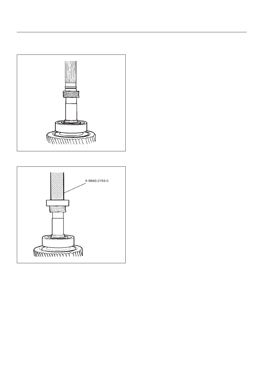
6. Install ball bearing (8), using the ball bearing installer

5–8840–2159–0 (J–37223).

226RW188

7. Install the rear output shaft assembly (1) to the

transfer rear cover.

8. Install the bearing snap ring (3).

NOTE: The snap ring must be fully inserted into the
transfer rear case snap ring groove.

TRANSFER CASE (STANDARD TYPE)

4D1–19

Transfer Rear Cover Assembly (Except 4WD Switch Model)

Transfer Rear Cover Assembly and Associated Parts

220RW116

Legend

(1) Speedometer Sensor, Speedometer Driven

Gear and Plate

(2) Front Companion Flange

(3) Rear Companion Flange
(4) Control Box Assembly
(5) Transfer Rear Cover Assembly
(6) Transfer Case Assembly

4D1–20 TRANSFER CASE (STANDARD TYPE)

Removal

1. Remove the speedometer sensor.
2. Remove the plate.
3. Remove the speedometer driven gear bushing and

driven gear.

NOTE: Apply a reference mark to the driven gear bushing
before removal.

4. Remove the front companion flange and the rear

companion flange, using the flange companion holder
5–8840–0133–0 (J–8614–11) to remove the end
nuts.

262RW067

NOTE: Use a universal puller to remove the rear
companion flange.

5. Disconnect the transfer breather hose from the

control box.

6. Remove the control box assembly.
7. Remove the transfer rear cover assembly from the

transfer case assembly.

Installation

1. Apply the recommended liquid gasket (LOCTITE

17430) or its equivalent to the transfer rear cover
fitting faces.

220RS017

2. Install the transfer rear cover assembly to the transfer

case assembly.

3. Perform the following steps before fitting the transfer

rear case:
1. Shift the high–low shift rod to the 4H side.

2. Turn the select rod counterclockwise so that the

select block projection may enter into the
2WD–4WD shift block.

3. The cut–away portion of the select rod head (9)

should align with that of the rear case hole’s
stopper (10).

230RW004

4. Tighten the transfer rear case bolts to the specified

torque.

Torque: 37 N·m (3.8kg·m/27 lb ft)

TRANSFER CASE (STANDARD TYPE)

4D1–21

5. Install the control box assembly.

Torque: 19 N·m (1.9kg·m/14 lb ft)

6. Connect the breather hoses to the control box.
7. Install the rear companion flange and front

companion flange, using the companion flange holder
5–8840–0133–0 (J–8614–11) to tighten the flange
nuts to the transfer case.

262RW067

8. Tighten the new transfer flange nuts to the specified

torque.

Torque
Rear companion flange: 167 N·m (17.0kg·m/123
lb ft)
Front companion flange: 137 N·m (14.0kg·m/101
lb ft)

9. Use the punch 5–8840–2293–0 (J–39209) to stake

the rear companion flange nut at two spots.

266RW027

266RW002

10. Stake the front companion flange nut at one spot.

NOTE: Be sure to confirm that there is no crack at the
staked portion of the flange nut after staking.

11. Install the O–ring (8) to the speedometer driven gear

bushing (7).

12. Install the driven gear to the speedometer driven gear

bushing (7).

13. Install the speedometer driven gear assembly to the

transfer rear cover.

14. Install the plate (6) to the transfer rear case and

tighten to the specified torque.

Torque: 15 N·m (1.5kg·m/11 lb ft)


Content   ..  1062  1063  1064  1065   ..