Opel Frontera UBS. Manual - part 26


  Index      Opel     Opel Frontera UBS - service repair manual 1998-2002 year


Search            


Content   ..  24  25  26  27   ..


Opel Frontera UBS. Manual - part 26


1A – 20 HEATING AND VENTILATION

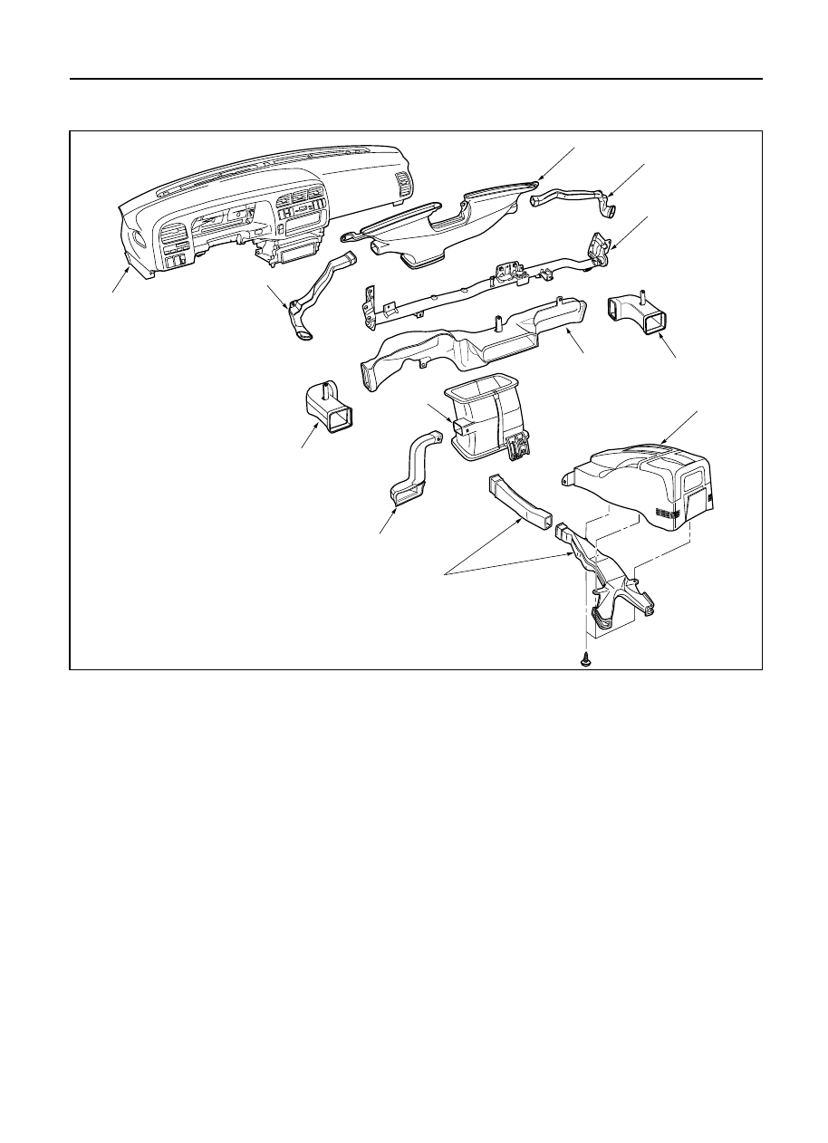
REAR HEATER DUCT, DEFROSTER NOZZLE AND VENTILATION DUCT

Removal Steps

1. Instrument panel assembly
2. Center ventilation upper duct
3. Side ventilation duct
4. Center ventilation lower duct
5. Driver lap duct
6. Center console
7. Rear heater duct
8. Cross beam assembly
9. Side defroster nozzle

10. Center defroster nozzle

Installation Steps

To install, follow the removal steps in the
reverse order.

7

9

9

10

8

6

3

5

1

3

4

2

This illustration is based on LHD

HEATING AND VENTILATION  1A – 21

INSTALLATION

To install, follow the removal steps in the reverse order,
noting the following point: 

1. Connect each duct and nozzle securely leaving no

clearance between them and making no improper
matching.

REMOVAL

Preparation:

Disconnect the battery ground cable 

1. Instrument panel assembly

Refer to Section 10 “BODY” for INSTRUMENT
PANEL ASSEMBLY removal procedure. 

2. Center ventilation upper duct 

3. Side ventilation duct 

4. Center ventilation lower duct 

5. Driver lap duct 

6. Center console

7. Rear heater duct

Refer to Section 10 “BODY” for CONSOLES
removal procedure. 

8. Cross beam assembly 

Refer to Section 10 “BODY” for CROSS BEAM
ASSEMBLY removal procedure. 

9. Side defroster nozzle 

10. Center defroster nozzle 

1A – 22 HEATING AND VENTILATION

Removal Steps

1. Front console assembly
2. Lower cluster assembly
3. Instrument panel driver lower

cover assembly

4. Meter cluster assembly
5. Center vent
6. Side vent

Installation Steps

To install, follow the removal steps in the
reverse order.

CENTER AND/OR SIDE VENT

6

5

3

1

2

4

This illustration is based on LHD

740RW168

HEATING AND VENTILATION  1A – 23

INSTALLATION

To install, follow the removal steps in the reverse order.

REMOVAL

1. Front console assembly

2. Lower cluster assembly

3. Instrument panel driver lower cover assembly

4. Meter cluster assembly

Refer to Section 10 “BODY” for INSTRUMENT
PANEL ASSEMBLY removal procedure.

5. Center vent

Remove screws and the center vent from center
cluster while prying up the center vent catch
portions.

6. Side vent

Remove screws and the side vent from center
cluster while prying up the side vent catch
portions.


Content   ..  24  25  26  27   ..