Opel Frontera UBS. Manual - part 23


  Index      Opel     Opel Frontera UBS - service repair manual 1998-2002 year


Search            


Content   ..  21  22  23  24   ..


Opel Frontera UBS. Manual - part 23


1A – 8 HEATING AND VENTILATION
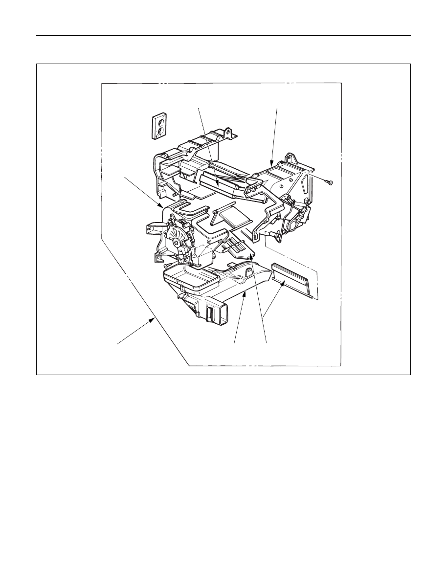
Removal Steps

1. Heater unit
2. Duct
3. Case (Mode control)
4. Case (Temperature control)
5. Heater core
6. Mode door

Installation Steps

To install, follow the removal steps in the
reverse order.

HEATER CORE AND/OR MODE DOOR

4

5

3

2

1

6

This illustration is based on LHD

HEATING AND VENTILATION  1A – 9

REMOVAL

Preparation:

Disconnect the battery ground cable

Drain engine coolant 

1. Heater Unit

Refer to “HEATER UNIT” removal procedure in this
section. 

2. Duct 

3. Case (Mode Control)

Do not remove link unit at this step.

4. Case (Temperature Control)

Separate two halves of core case.

Heater core

5. Heater Core

Heater core

6. Mode Door

Pull out the mode door while raising up the catch of
the door lever.

INSTALLATION

To install, follow the removal steps in the reverse order,
noting the following point: 

1. Check that each mode door operates properly.

1A – 10 HEATING AND VENTILATION

Removal Steps

1. Heater unit
2. Case (Mode control)
3. Washer and mode main lever
4. Rod
5. Mode sub-lever
6. Door lever
7. Clip

Installation Steps

To install, follow the removal steps in the
reverse order.

HEATER MODE CONTROL LINK UNIT

This illustration is based on LHD

1

2

5

6

7

3

4

5

4

6

7

5

HEATING AND VENTILATION  1A – 11

REMOVAL

Preparation:

Disconnect the battery ground cable

Drain engine coolant 

1. Heater Unit

Refer to “HEATER UNIT” removal procedure in this
section. 

2. Case (Mode Control)

Remove the case (Mode control) from heater unit. 

3. Washer and Mode Main Lever 

4. Rod

5. Mode Sub-Lever

Press the tab of the sub-lever inward, and take out the
sub-lever.

6. Door Lever

Pull out the door lever while raising up the catch of
the door lever. 

INSTALLATION

To install, follow the removal steps in the reverse order,
noting the following points: 

1. Apply grease to mode sub-lever and to the abrasive

surface of the heater unit.

2. After installing the link unit, check to see if the link

unit operates correctly. 


Content   ..  21  22  23  24   ..