Opel Frontera UBS. Manual - part 22
1A – 4 HEATING AND VENTILATION
AIR SELECT KNOB
The air selector knob allows you to direct heated air
into the passenger compartment through different
outlets.
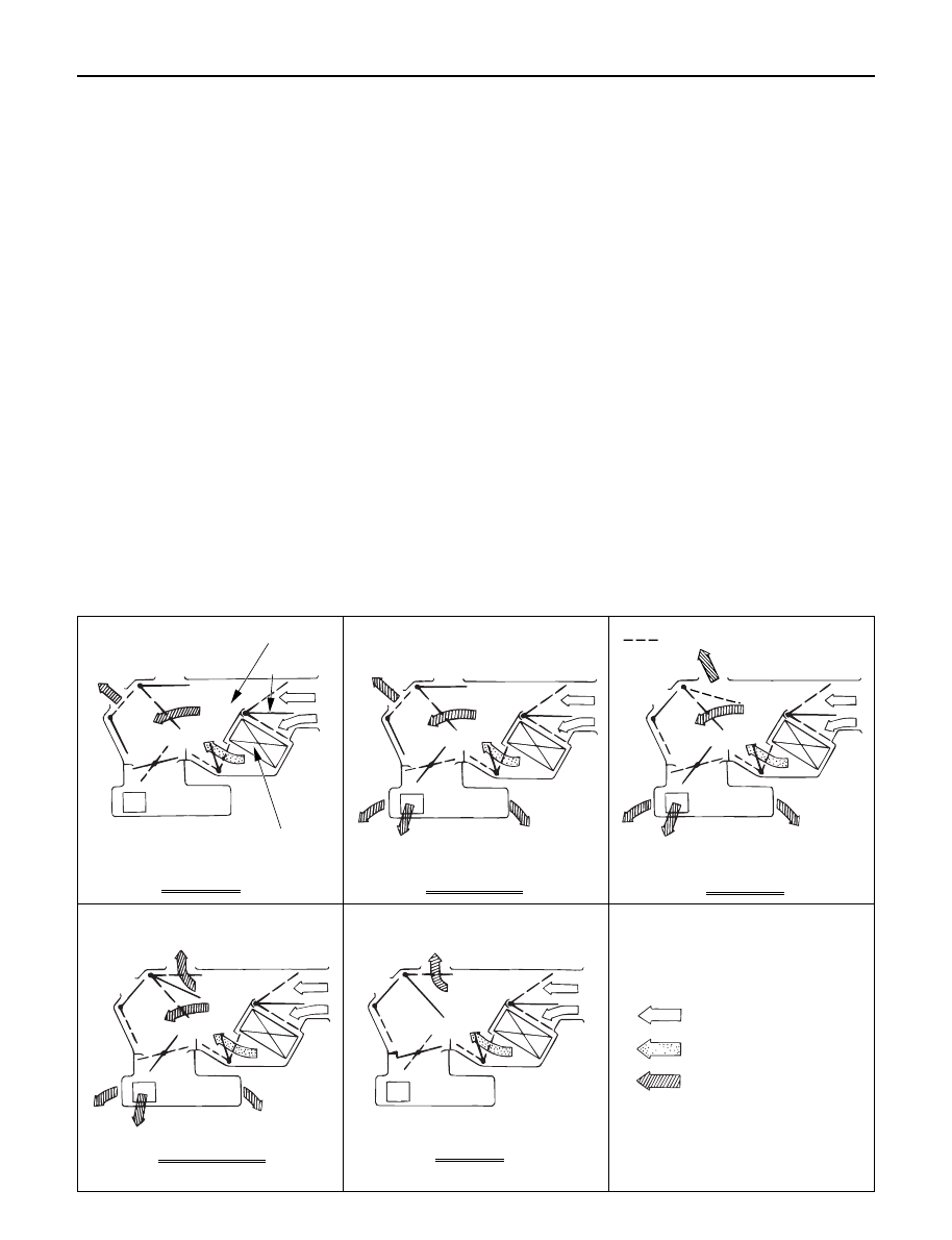
1.
Vent - In this position, air is discharged from
the upper air outlet. Air quantity is controlled
by the fan control knob.
2.
Bi-Level - In this position, air flow is divided
between the upper air outlets and the foot air
outlets, with warmer air delivered to the floor
outlets than the air delivered to the upper air
outlets.
3.
Foot - In this position, air flow is delivered to
the foot while sending approx. 30% of total
amount of air to the windshield
4.
Def/Foot - In this position, air flow is delivered
to the foot, while sending approx. 40% of total
amount of air to the windshield.
5.
Defrost - In this position, most of the air is
delivered to the windshield and a small
amount is delivered to the side windows.
Moving the air source select lever to the “CIRC”
position provides quickest heat delivery by closing
the blower assembly mode door. In this position,
outside air is not delivered to the passenger
compartment.
AIR SOURCE SELECT LEVER
The intake of outside air and the circulation of inside
air are controlled by sliding this lever left or right.
FAN CONTROL KNOB
This knob controls the blower motor speed to
regulate the amount of air delivered to the defrost,
foot, and ventilation ducts:
1.
Low
2.
Medium Low
3.
Medium High
4.
High
TEMPERATURE CONTROL KNOB
When the temperature control knob is in the
“COLD” position, the air mix door closes to block
the flow of air to the heater core.
When the temperature control knob is in the
“HOT” position, the air mix door opens to allow air
to pass through the heater core and heat the
passenger compartment.
Placing the knob in an intermediate position will
cause a lesser or greater amount of air to reach the
heater core. In this mode the passenger compart-
ment temperature can be regulated.
Heater core
Heater unit
TO VENT OUTLET
Air mix door
VENT MODE
TO FOOT
TO VENT OUTLET
BI-LEVEL MODE
FOOT MODE
TO FOOT OUTLET
TO DEF OUTLET(LHD)
DEF/FOOT MODE
TO FOOT OUTLET
TO DEF OUTLET
DEF MODE
TO DEF OUTLET
: COLD AIR
: HOT AIR
: TEMP.CONTROLLED AIR