Opel Frontera UE. Manual - part 952


  Index      Opel     Opel Frontera UE - service repair manual 1999-2001 year


Search            copyright infringement  


Content   ..  950  951  952  953   ..


Opel Frontera UE. Manual - part 952


6E2–194

6VD1 3.2L ENGINE DRIVEABILITY AND EMISSIONS

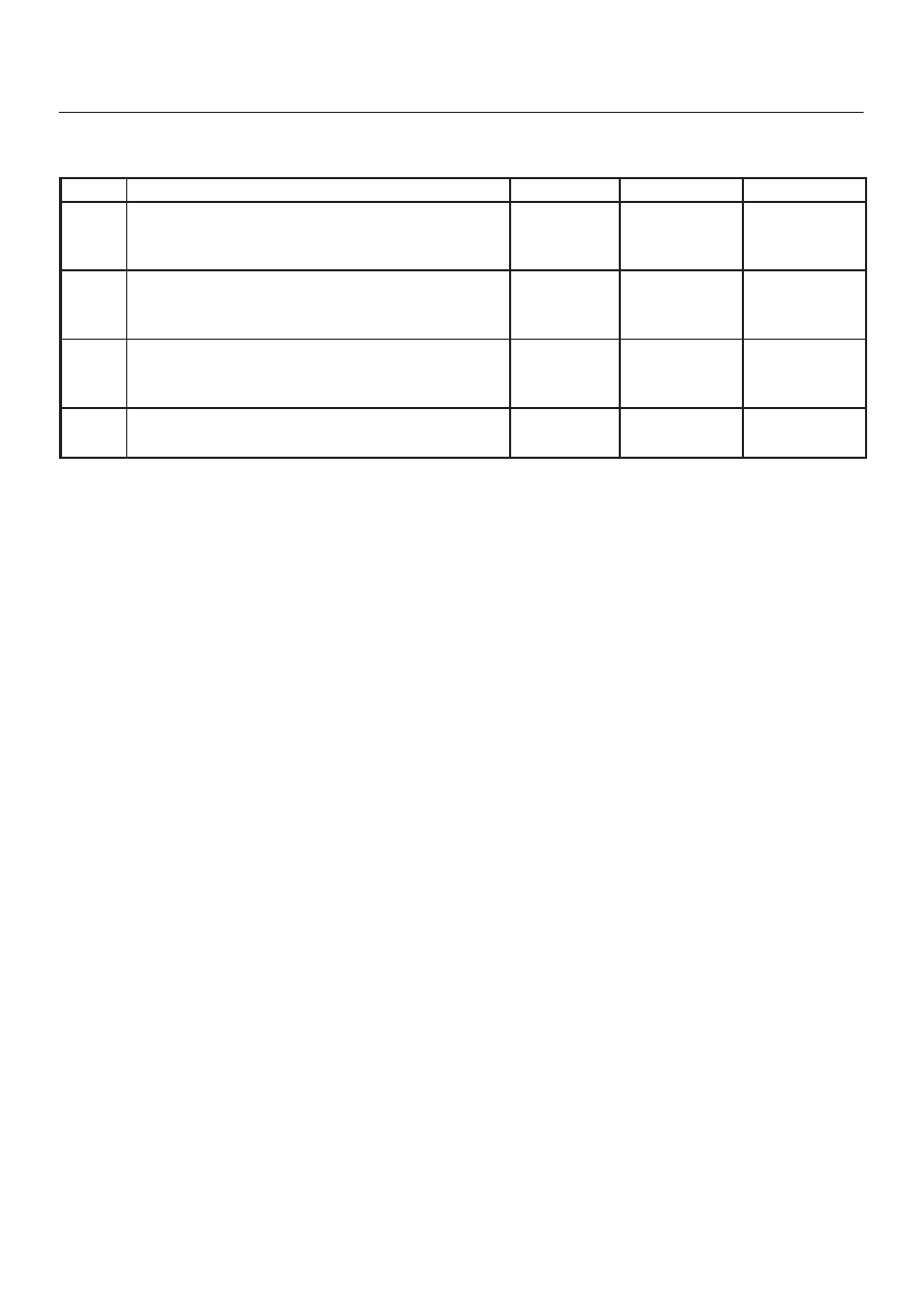
DTC P0337 – CKP Sensor Circuit Low Frequency

  (Cont'd)

Step

No

Yes

Value(s)

Action

9

Check the connections at the CKP sensor and replace
the terminals if necessary.

Did any terminals require replacement?

Verify repair

Go to 

Step 10

10

Replace the CKP sensor.  Use caution and avoid hot oil
that may drip out.

Is the action complete?

Verify repair

11

Check the connections at the PCM and replace the
terminals if necessary.

Did any terminals require replacement?

Verify repair 

Go to 

Step 12

12

Replace the PCM.

Is the action complete?

Verify repair

6E2–195

6VD1 3.2L ENGINE DRIVEABILITY AND EMISSIONS

Diagnostic Trouble Code (DTC) P0341 CMP Sensor Circuit Performamce

D06RX145

Circuit Description

The CMP signal is produced by the camshaft position
(CMP) sensor pulses when the engine is running and
crankshaft position (CKP) sync pulses are also being
received.  The powertrain control module (PCM) uses the
CMP signal pulses to initiate sequential fuel injection.
The PCM constantly monitors the number of pulses on
the CMP signal circuit and compares the number of CMP
pulses to the number of 58X reference pulses received.  If
the PCM receives an incorrect number of pulses on the
CMP reference circuit, DTC P0341 will set and the PCM
will initiate injector sequence without the CMP signal with
a one in six chance that injector sequence is correct.  The
engine will continue to start and run normally, although
the misfire diagnostic will be affected if a misfiring
condition occurs.

Conditions for Setting the DTC

D

The engine is running (1X CMP reference pulses are
being received).

D

The CMP sensor signal is not detected at the correct
interval every 6 cylinders.

D

Above condition fails for 100 occurrences within 200
test samples.

Action Taken When the DTC Sets

D

The PCM will illuminate the malfunction indicator lamp
(MIL) after the second consecutive trip in which the
fault is detected.

D

The PCM will initiate the injector sequence without the
CMP signal with a one in six chance that the injector
sequence is correct.

D

The PCM will store conditions which were present
when the DTC was set as Freeze Frame and in the
Failure Records data.

6E2–196

6VD1 3.2L ENGINE DRIVEABILITY AND EMISSIONS

Conditions for Clearing the MIL/DTC

D

The PCM will turn the MIL “OFF” on the third
consecutive trip cycle during which the diagnostic has
been run and the fault condition is no longer present.

D

A history DTC P0341 will clear after 40 consecutive
warm-up cycles have occurred without a fault.

D

DTC P0341 can be cleared by using the Tech 2 “Clear
Info” function or by disconnecting the PCM battery
feed.

Diagnostic Aids

An intermittent may be caused by a poor connection,
rubbed–through wire insulation or a wire broken inside the
insulation.  Check for:

D

Poor connection — Inspect the PCM harness and
connectors for improper mating, broken locks,
improperly formed or damaged terminals, and poor
terminal-to-wire connection.

D

Damaged harness — Inspect the wiring harness for
damage.  If the harness appears to be OK, disconnect
the PCM, turn the ignition on and observe a voltmeter
connected to the CMP signal circuit at the PCM
harness connector while moving connectors and
wiring harnesses related to the ICM and the CMP

sensor.  A change in voltage will indicate the location
of the fault.

Reviewing the Failure Records vehicle mileage since the
diagnostic test last failed may help determine how often
the condition that caused the DTC to be set occurs.  This
may assist in diagnosing the condition.
NOTE: On early-built Troopers, the Tech 2 indication for
“CMP ACT. COUNTER” (Cam Position Sensor activity)
will continue to count up, even if no cam position signal is
being received by the PCM.  This problem can be
corrected by reprogramming the PCM with the latest
EEPROM program.

Test Description

Number(s) below refer to the step number(s) on the
Diagnostic Chart.
2. Ensures that the fault is present.

10.Determines whether the fault is being caused by a

missing camshaft magnet or a faulty sensor.  The
voltage measured in this step should read around 4
volts, toggling to near 0 volts when the CMP sensor
interfaces with the camshaft magnet.

DTC P0341 —CMP Sensor Circuit Performance


Step

Action

Value(s)

Yes

No

1

Was the “On-Board Diagnostic (OBD) System Check”
performed?

Go to 

Step 2

Go to 

OBD

System

Check

2

1. Ignition “ON.”
2. Review and record Tech 2 Failure Records data.
3. Operate the vehicle within Failure Records

conditions as noted.

4. Using a Tech 2, monitor “DTC” info for DTC P0341

until the DTC P0341 test runs.

5. Note the test result.

Does the Tech 2 indicate DTC P0341 failed this
ignition?

Go to 

Step 3

Refer to

Diagnostic

Aids

3

Measure the voltage between the CMP sensor signal
circuit and the sensor ground circuit at the CMP sensor
harness connector.

Does the voltage measure near the specified value?

4-6 V

Go to 

Step 10

Go to 

Step 7

4

If the voltage measured in step 3 was less than 4-6
volts, proceed directly to step 6 without completing this
step.
If the voltage in step 3 was greater than 4-6 V, repair the
short to voltage in the CMP feed circuit.

Is the action complete?

Verify repair

5

1. Check for poor connections at the camshaft

position sensor.

2. If a problem is found, repair it as necessary.

Was a problem found?

Verify repair

Go to 

Step 6

6E2–197

6VD1 3.2L ENGINE DRIVEABILITY AND EMISSIONS

DTC P0341 —CMP Sensor Circuit Performance

  (Cont'd)

Step

No

Yes

Value(s)

Action

6

1. Ignition “OFF,” disconnect the PCM and the CMP

sensor.

2. Check the following circuits for an open between the

ignition control module and the CMP sensor:

D

The sensor feed circuit.

3. If a problem is found, repair as necessary.

Was a problem found?

Verify repair 

Go to 

Step 8

7

1. Ignition “OFF,” disconnect the PCM (leave the CMP

sensor disconnected).

2. Ignition “ON,” check the following circuits:

D

The CMP sensor signal circuit for an open or a
short to voltage.

D

The CMP sensor input signal circuit for a short
to ground.

3. If a problem is found, repair it as necessary.

Was a problem found?

Verify repair

Go to 

Step 8

8

Check for a short or open in the sensor ground circuit.

Was a problem found?

Verify repair

Go to 

Step 9

9

1. Check for poor connections at the PCM.
2. If a problem is found, repair it as necessary.

Was a problem found?

Verify repair

Go to 

Step 10

10

Backprobe the PCM connector with a DVM to monitor
voltage on the camshaft position input signal circuit
while cranking the engine with the sensor connected.
(Use rubber band, tape, or an assistant to keep the
DVM lead in contact with the sensor terminal during this
test.)

Does the voltage toggle between the specified values?

4-0 V

Go to 

Step 10

Go to 

Step 11

11

1. Remove the CMP sensor.

Does the DVM display a voltage near the specified
value?

Go to 

Step 12

Go to 

Step 13

12

Replace the faulty or missing camshaft position sensor.

Is the action complete?

Verify repair

13

Replace the camshaft position sensor.

Is the action complete?

Verify repair

14

Replace the PCM.

Is the action complete?

Verify repair


Content   ..  950  951  952  953   ..