Opel Frontera UE. Manual - part 862
6H–2
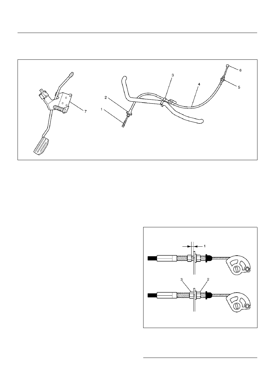
ENGINE SPEED CONTROL SYSTEM (X22SE 2.2L)
Accelerator Pedal Control Cable
035RX004
Removal
1. Loosen the nut(5) on the cable bracket mounted.
2. Remove cable clip(3).
3. Disconnect accelerator pedal (AP) control cable(6).
(on throttle valve side)
4. Disconnect AP control cable(1). (on AP pedal(7)
side)
5. Remove grommet(2).
6. Remove AP control cable(4).
Inspection
Check the following items, and replace the control cable
if any abnormality is found:
• The control cable should move smoothly.
• The control cable should not be bent or kinked.
• The control cable should be free of damage and
corrosion.
Installation
1. Install AP control cable(4).
2. Install grommet(2).
3. Connect AP control cable(1). (on AP pedal(7) side)
4. Connect AP control cable(6). (on throttle valve side)
5. Install cable clip(3).
6. Install nut(5).
Adjustment
1. Loosen adjusting nut and lock nut.
2. Pull outer cable while closing fully the throttle valve.
3. Tighten adjusting nut and lock nut temporarily.
4. Loosen adjusting nut by three turns and tighten lock
nut.
Then, manually operating the throttle valve, make
sure that the valve lever returns up to the stopper
screw.
If it does not reach the stopper screw, repeat from
step 1.
035RX014
Legend
EndOFCallout
(1) Clearance (2 – 3.5 mm)
(2) Lock Nut
(3) Adjusting Nut