Opel Frontera UE. Manual - part 778
6D3–10
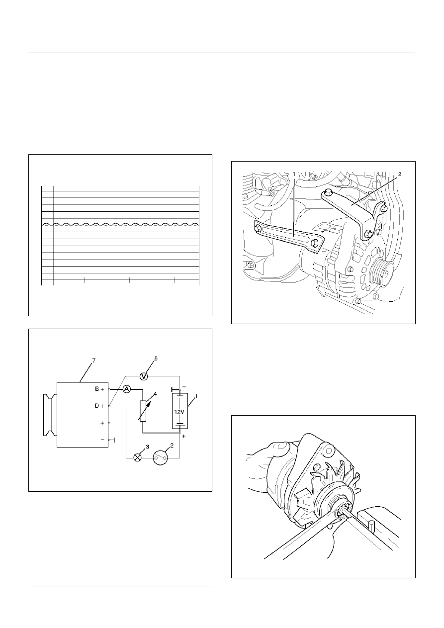
STARTING AND CHARGING SYSTEM (X22SE 2.2L)
Generator Power
1. Adjust load resistor, if the required load currents are
not attained.
2. The shape of the voltage curves on oscilloscope
curve should be regular.
3. Test value: 5 to 7A.
4. If the required minimum current intensity is not
attained, or if the oscilloscope picture shows
variations, the alternator should be overhauled.
066RW018
Regulated Voltage Circuit Diagram
066RW019
Legend
EndOFCallout
Installation
1. Install generator assembly and bring generator
assembly to the position to be installed.
2. Install generator bracket (1), (2) and tighten to the
specified torque.
Torque:
Long bolt: 35 N·m (3.6 kg·m/26 lb ft)
Short bolt: 20 N·m (2.0 kg·m/15 lb ft)
065RW025
3. Connect wiring harness connector.
4. Move drive belt tensioner to loose side using
wrench, then install drive belt to normal position.
5. Reconnect battery ground cable.
Disassembly
1. Belt pulley nut.
066RW016
(1) Battery
(2) Ignition Lock
(3) Charge Telltale
(4) Resistor, for attainment of load current with the
battery set in series
(5) Voltmeter
(6) Ammeter
(7) Generator