Opel Frontera UE. Manual - part 764


  Index      Opel     Opel Frontera UE - service repair manual 1999-2001 year


Search            


Content   ..  762  763  764  765   ..


Opel Frontera UE. Manual - part 764


ENGINE MECHANICAL (X22SE 2.2L)

6A–65

Removal

1. Remove two bolts and remove ignition cable cover 

(1) from cylinder head cover (3).

2. Disconnect ignition cable and remove spark plag 

(2).

3. Disconnect ignition cable from ignition plug.

4. Disconnect camshaft angle sensor harness and 

crankshaft angle sensor harness from behind 
generator.

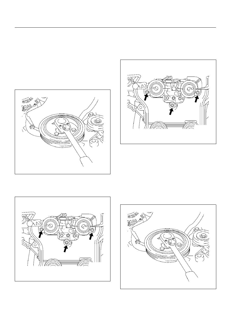
5. Remove four bolts and remove the crankshaft pulley. 

020RW014

6. Remove timing belt front cover.

7. Loose fixing bolt of timing belt rear cover, then 

remove the camshaft angle sensor.

020RW012

8. Remove ten cylinder head cover fixing bolts and 

remove the cylinder head cover.

Installation

1. Install the camshaft angle sensor and tighten timing 

rear cover bolt.

Torque: 8 N·m (0.8Kg·m/5.9lbft)

020RW012

2. Install the cylinder head cover and tighten bolts to 

the specified torque.

Torque: 8 N·m (0.8Kg·m/5.9lbft)

3. Install the timing belt front cover then tighten fixing 

bolts to the specified torque.

Torque: 6 N·m (0.6Kg·m/4.4lbft)

4. Install the crankshaft pulley, tighten fixing bolts to 

the specified torque.

Torque: 20 N·m (2.0Kg·m/14lbft)

020RW014

6A–66

ENGINE MECHANICAL (X22SE 2.2L)

5. Move drive belt tensioner to loose side using wrench 

then install the drive belt to normal position.

033RW001

6. Connect ignition cable to ignition plug.

7. Install ignition cable cover to cylinder head cover 

and tighten two bolts to the specified torque.

Torque: 3 N·m (0.3Kg·m/2lbft)

ENGINE MECHANICAL (X22SE 2.2L)

6A–67

Balance Unit Assembly

Balance Unit Assembly Associated Parts

051RW012

Legend

EndOFCallout

(1) Oil Pan
(2) Oil Pan Support
(3) Oil Strainer

(4) Balance Unit Assembly
(5) Shim

6A–68

ENGINE MECHANICAL (X22SE 2.2L)

Disassembly

1. Remove the oil pan.

2. Remove the oil pan support.

3. Remove the oil strainer (1) from oil pump and the oil 

baffle plate (2).

051RW009

Adjustment

1. Turn crankshaft in engine rotational direction to 

alignment mark (2) 1st cylinder “TDC".

014RW066

2. In this crankshaft position, the flattened side 

(arrows) of both balancer shafts must face 
downward and must be on a horizontal line.

051RW010

3. Screw measuring device 5–8840–2671–0 (3) with 

long knurled bolt (1) into 1st balancer shaft (intake 
side) and tighter hard–tight measuring arm (5) must 
point in “9 o'clock" direction shown in this illustration.
Install dial gauge holder with dial gauge (4) on 
cylinder block.

051RW007


Content   ..  762  763  764  765   ..