Opel Frontera UE. Manual - part 762
ENGINE MECHANICAL (X22SE 2.2L)
6A–57
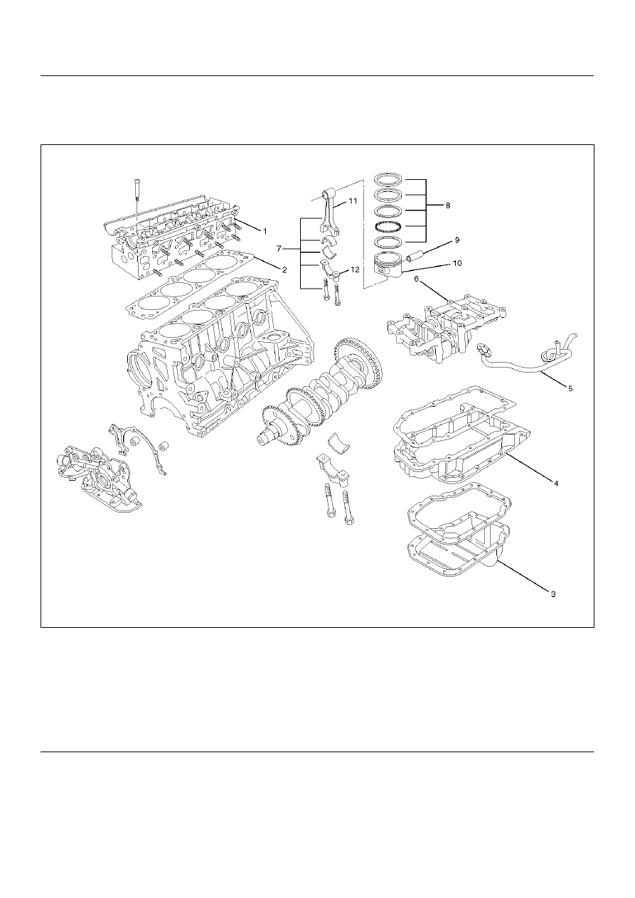
Piston and Connecting Rod
Piston, Connecting Rod and Associate Parts
015RW037
Legend
EndOFCallout
Disassembly
1. Remove cylinder head assembly (1), refer to
“Cylinder Head Removal" in this manual.
2. Remove cylinder head gasket (2).
3. Remove oil pan assembly and oil pan support (3)
refer to“Oil Pan and Oil Pan Support" in this manual.
4. Remove oil strainer.
5. Remove balance unit assembly.
6. Remove connecting rod cap with connecting rod
lower.
(1) Cylinder Head Assembly
(2) Cylinder Head Gasket
(3) Oil Pan Assembly
(4) Pan Support
(5) Oil Strainer
(6) Balance Unit Assembly
(7) Piston and Connecting Rod Assembly
(8) Piston Ring
(9) Piston Pin
(10) Piston
(11) Connecting Rod
(12) Connecting Rod Cap