Opel Frontera UE. Manual - part 761


  Index      Opel     Opel Frontera UE - service repair manual 1999-2001 year


Search            


Content   ..  759  760  761  762   ..


Opel Frontera UE. Manual - part 761


ENGINE MECHANICAL (X22SE 2.2L)

6A–53

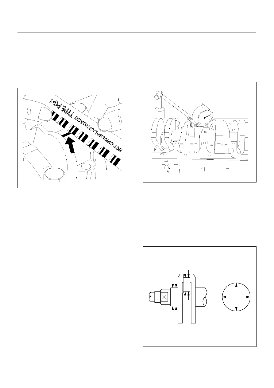
10. Measure the plastigage width and determine the oil 

clearance. If the oil clearance exceeds the specified 
limit, replace the main bearings as a set and/or 
replace the crankshaft.

Standard : 0.015 mm–0.04 mm

(0.0007 in–0.0016 in)

Limit : 0.12 mm (0.0047 in)

014RW077

11. Clean the plastigage from the bearings and the 

crankshaft.
Remove the crankshaft and the bearings.

Crankshaft (12) Inspection

Inspect the surface of the crankshaft journal and crank 
pins for excessive wear and damage. Inspect the oil 
seal fitting surfaces for excessive wear and damage. 
Inspect the oil ports for obstructions.

Inspection and Repair

1. Carefully set the crankshaft. Slowly rotate the 

crankshaft and measure the runout. If the 
crankshaft runout exceeds the specified limit, the 
crankshaft must be replaced.

Runout : 0.03 mm (0.0012 in)

014RW078

2. Measure the diameter and the uneven wear of main 

journal and crank pin. If the crankshaft wear 
exceeds the specified limit, crankshaft must be 
replaced.

Main journal diameter : 57.934 mm–57.980 mm

(2.259 in–2.261 in)

Crank pin diameter : 48.939 mm–48.982 mm

(1.909 in.–1.91 in.)

015RS009

6A–54

ENGINE MECHANICAL (X22SE 2.2L)

Crankshaft Bearing Selection

When installing new crankshaft bearings or replacing 
bearings, refer to the selection table below. Select and 
install the new crankshaft bearings.

NOTE:  Take care to ensure the bearings are positioned 
correctly.
Crankshaft pulse pickup sensor disc inspection and 
repair.
Inspect the crankshaft pulse pickup sensor disc for 
excessive wear and damage.
Replace the crankshaft pulse pickup sensor disc if the 
inspection exceeds wear and damage.

015RW039

Reassembly

1. Crankshaft (12).

• Install the crankshaft pulse pickup sensor disc.

Torque: 13 N·m (1.3Kg·m/10lbft)

• Install the main bearings to the cylinder block and 

the main bearing caps.

• Be sure that they are positioned correctly.

• Apply new engine oil to the upper and lower main 

bearing faces.

NOTE:  Do not apply engine oil to the main bearing 
back faces.

• Carefully mount the crankshaft.

• Apply engine oil to the thrust washer.

• Assemble the thrust washer to the No.3 bearing 

journal. The oil grooves must face the crankshaft.

• Tighten the crankshaft baring cap bolts in 3 

steps:

1st step: 50 N·m (5.1Kg·m/36lbft)

2nd step: 45

°°°°

3rd step: 15

°°°°

Crankshaft grinding dimensions

mm  (in)

Production and Service

Crankshaft bearing journal dia.

Standard size

white

57.974 to 57.981 (2.260–2.261)

green

57.981 to 57.988 (2.261–2.2615)

brown

57.988 to 57.995 (2.2615–2.2618)

Undersize 0.25 (0.0097)

green/blue

57.732 to 57.738 (2.2515–2.2517)

brown/blue

57.738 to 57.745 (2.2517–2.252)

Undersize 0.5 (0.0195)

green/white

57.482 to 57.488 (2.2418–2.242)

brown/white

57.488 to 57.495 (2.242–2.2423)

Guide bearing width

Standard size

25.950 to 26.002 (1.012–1.014)

Undersize 0.25 (0.0097)

26.150 to 26.202 (1.019–1.021)

Undersize 0.5 (0.0195)

26.350 to 26.402 (1.027–1.029)

ENGINE MECHANICAL (X22SE 2.2L)

6A–55

2. Rear oil seal (10).

• Coat lip of seal rings thinly with protective grease.

• Install seal ring into cylinder block, use 5–8840–

2660–0 (1) and 5–8840–2597–0 (2).

015RW009

3. Flywheel (9).

1. Thoroughly clean and remove the oil from the 

threads of crankshaft.

2. Remove the oil from the crankshaft and flywheel 

mounting faces.

3. Mount the flywheel on the crankshaft and then 

install the washer.

4. Use stopper (5–8840–2661–0) to hold the 

crankshaft.

015RW010

5. Prevent from rotating.

Tighten the flywheel bolts in 3 steps:

1st step: 65 N·m (6.6Kg·m/48lbft)

2nd step: 30

°

3rd step: 15

°

NOTE:  Do not reuse the bolt.

4. Piston and connecting rod assembly (8)

• Apply engine oil to the cylinder bores, the 

connecting rod bearings and the crankshaft pins. 
Check to see that the piston ring end gaps are 
correctly positioned.

• Piston rings position (A) every 180

°.

Oil scraper rings (B) — offset 25 to 50 mm/1 to 2 
in. to left and right from gap of intermediate ring.

015RW026

• Insert the piston/connecting rod assemblies into 

each cylinder with the piston ring compressor. 
The front marks must be facing the front of the 
engine.

• Match the numbered caps with the numbers on 

the connecting rods. Align the punched marks on 
the connecting rods and caps.

• Arrow (1) on piston head points to engine timing 

side, bead on connecting rod points to flywheel 
side.

015RW038

6A–56

ENGINE MECHANICAL (X22SE 2.2L)

• Tighten the bolts in 3 steps:

1st step: 35 N·m (3.6Kg·m/25lbft)

2nd step: 45

°°°°

3rd step: 15

°°°°

5. Install the balance unit assembly and tighten the 

bolts in 2 steps:

1st step: 20 N·m (2.0Kg·m/14lbft)

2nd step: 45

°°°°

Refer to the “Balance Unit Assembly" section of this 
manual.

6. Install oil pump assembly (5), refer to “Oil Pump" in 

this manual.

7. Install oil strainer.

Torque: 8 N·m (0.8Kg·m/5.8lbft)

8. Install oil pan support and tighten the bolts to the 

specified torque.

Torque: 20 N·m (2.0Kg·m/14lbft)

9. Install oil pan.

1. Completely remove all residual sealant, 

lubricant and moisture from the sealing 
surfaces. The surfaces must be perfectly dry.

2. Apply a correct width bead of sealant (TB–

1207C or its equivalent) to the contact surfaces 
of the oil pan. There must be no gaps in the 
bead.

3. The oil pan support must be installed within 5 

minutes after sealant application.

4. Tighten the bolts in to steps.

1st step: 8 N·m (0.8Kg·m/5.8lbft)

2nd step: 30

°°°°

10. Install cylinder head assembly, refer to “Cylinder 

Head" in this manual.


Content   ..  759  760  761  762   ..