Opel Frontera UE. Manual - part 740
5C–30
POWER-ASSISTED BRAKE SYSTEM
Special Tools
ILLUSTRATION
TOOL NO.
TOOL NAME
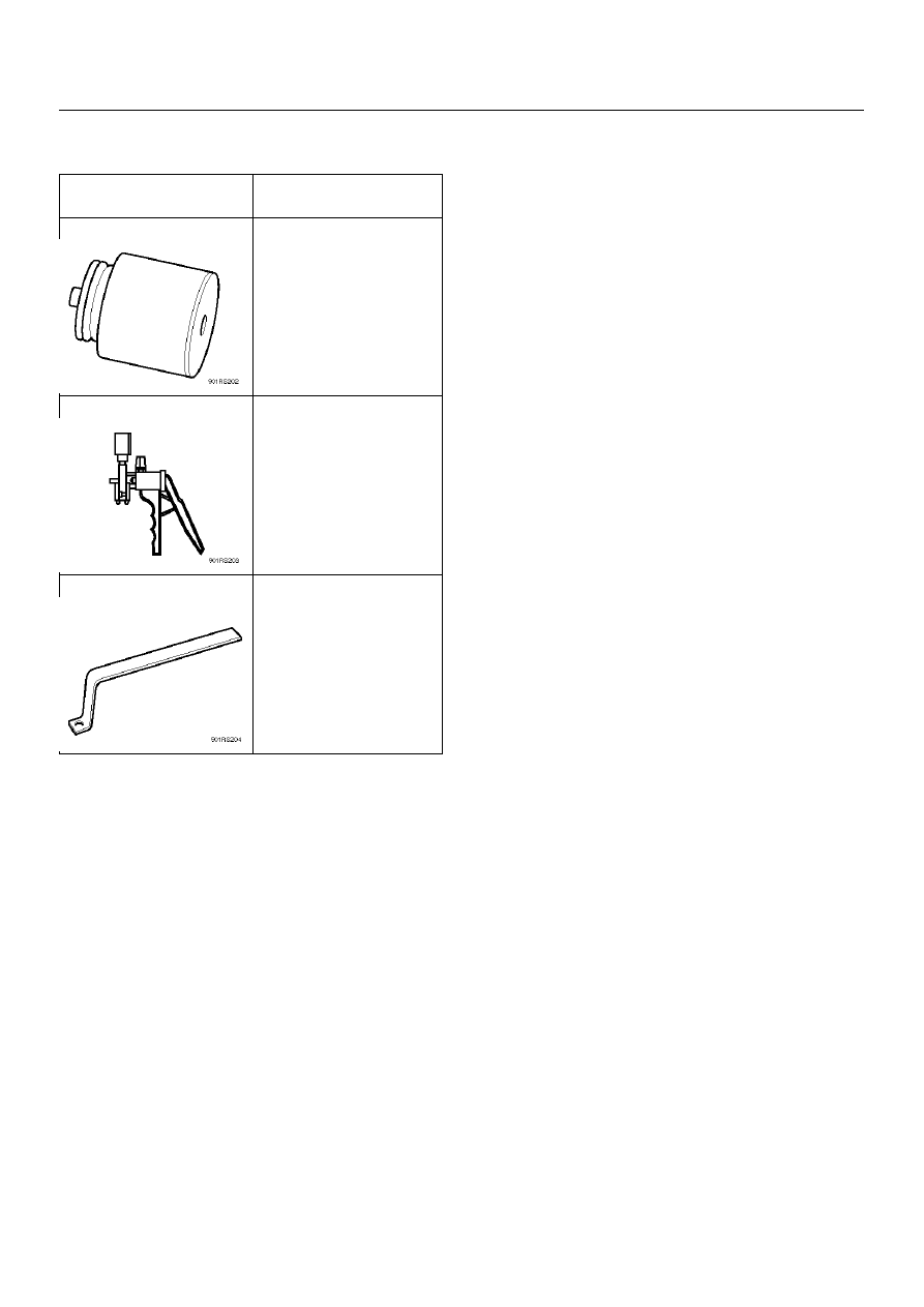
5-8840-2300-0
(J-39216)
Push Rod Gauge
5-8840-0279-0
(J-23738-A)
Vacuum Pump
5-8840-2305-0
(J-39241)
Push Rod Support
|
|
|
5C–30 POWER-ASSISTED BRAKE SYSTEM Special Tools ILLUSTRATION TOOL NO. TOOL NAME 5-8840-2300-0 (J-39216) Push Rod Gauge 5-8840-0279-0 (J-23738-A) Vacuum Pump 5-8840-2305-0 (J-39241) Push Rod Support |