Opel Frontera UE. Manual - part 737


  Index      Opel     Opel Frontera UE - service repair manual 1999-2001 year


Search            


Content   ..  735  736  737  738   ..


Opel Frontera UE. Manual - part 737


5C–18

POWER-ASSISTED BRAKE SYSTEM

5. Adjust pedal free travel.

Refer to Brake Pedal Adjustment in this section.

6. Tighten the steering column fixing bolt (9) (dash 

panel) to the specified torque.

Torque: 20 N·m (2.0 kg·m/14 lbft)

7. Tighten the steering column fixing nut (9) (Cross 

Beam) to the specified torque.

Torque: 17 N·m (1.7 kg·m/12 lbft)

8. Apply grease to the entire circumference of the 

Push rod pin (7).

9. Install push rod pin (7).

10. Install snap pin (4).

11. Connect the anti-theft control module connector.

Refer to Body and Accessories section.

12. Connect the stop light switch connector (3).

13. Install driver knee bolster (10) and lower cover (8).

14. Install the engine hood opening lever.

15. Connect the yellow 3 way SRS connector located 

under the steering column.

16. Connect the battery “–" terminal cable.
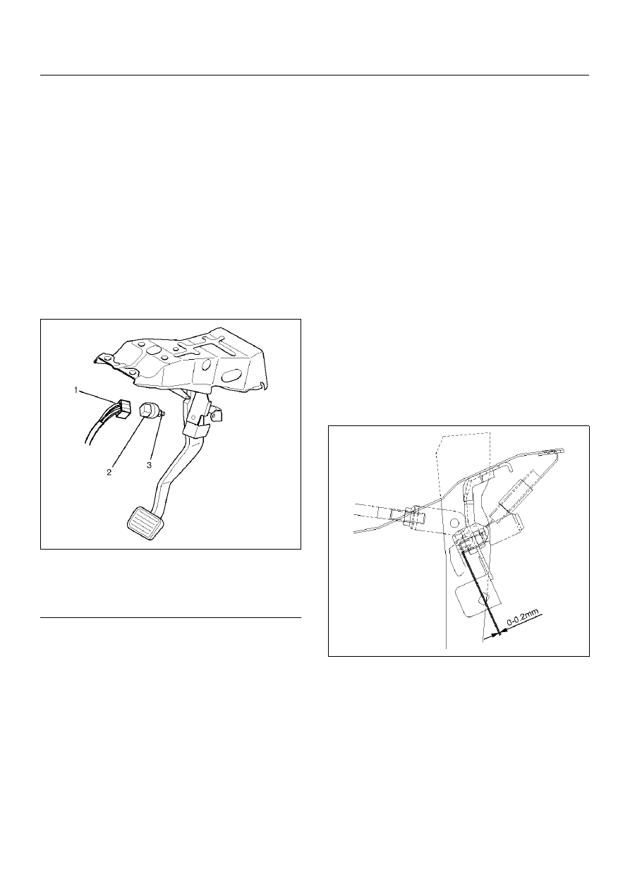
Stoplight Switch

Parts Location

310RW024

Legend

EndOFCallout

Removal

1. Disconnect connector (1)

2. Remove lock nut (3).

3. Remove switch (2).

Installation

1. Adjust the stop light switch to the specified 

clearance (between switch housing and brake 
pedal) by rotating the switch housing.

Clearance : 0-0.2 mm (0-0.008 in)

NOTE:  Do not attempt to force the push rod into 
position during the stop light switch installation and 
adjustment procedure.

310RW022

2. Connect connector (1).

3. Install lock nut (3).

(1) Connector
(2) Switch
(3) Lock Nut

POWER-ASSISTED BRAKE SYSTEM

5C–19

Main Data and Specifications

General Specifications

Torque Specifications

E05RX006

Pedal free play

6–10 mm (0.23 –0.39 in)

Pedal Height

173–185 mm (6.81–7.28 in)

5C–20

POWER-ASSISTED BRAKE SYSTEM

Fluid Reservoir Tank

Fluid Reservoir Tank and Associated Parts

330RW003

Legend

EndOFCallout

Removal

NOTE:  Before removing the fluid reservoir, remove the 
brake fluid from the fluid reservoir.

1. Disconnect electrical connector.

2. Remove retainer (1).

330RW004

3. Remove fluid reservoir and the fluid level sensor 

built into the fluid reservoir. The fluid level sensor 
cannot be removed for servicing.

4. Remove O–ring.

Installation

To install, follow the removal steps in the reverse order, 
noting the following points:

1. O–ring (1) must be set onto the fluid reservoir (2), 

before installing fluid reservoir.

330RW005

(1) Fluid Reservoir
(2) Electrical Connector

(3) O–ring
(4) Retainer

POWER-ASSISTED BRAKE SYSTEM

5C–21

Master Cylinder Assembly

Master Cylinder Assembly and Associated Parts

330RW010

Legend

EndOFCallout

Removal

CAUTION:  When removing the master cylinder from 
the vacuum booster, be sure to get rid of the 
internal negative pressure of the vacuum booster 
(by, for instance, disconnecting the vacuum hose) in 
advance.
If any negative pressure remains  in the vacuum 
booster, the piston may possibly come out when the 
master cylinder is being removed, letting the brake 
fluid run out.
 While removing the master cylinder, further, do not 
hold the piston as it can be easily pulled out.
Outside surface of the piston is the surface on 
which seals are to slide. Care should be taken to 
keep the surface free of cuts and dents.

1. Disconnect electrical connector.

2. Remove brake pipes and after disconnecting the 

brake pipe, cap or tape the openings of the brake 
pipe to prevent the entry of foreign matter.

3. Remove 2 attaching nuts.

4. Remove P&B valve and bracket.

5. Remove master cylinder.

6. Remove spacer and the 2 gaskets.

Inspection and Repair

Master Cylinder

The master cylinder is not repairable and must be 
replaced as a complete assembly if found defective.

Inspection

Excessive brake pedal travel, malfunction or dragging 
brake suggests that the master cylinder is defective. In 

(1) Electrical Connector
(2) Master Cylinder
(3) 2 attaching Nuts

(4) P&B Valve and Bracket
(5) Brake Pipes
(6) Spacer and 2 gaskets


Content   ..  735  736  737  738   ..