Opel Frontera UE. Manual - part 697


  Index      Opel     Opel Frontera UE - service repair manual 1999-2001 year


Search            


Content   ..  695  696  697  698   ..


Opel Frontera UE. Manual - part 697


DRIVE SHAFT SYSTEM

4C–7

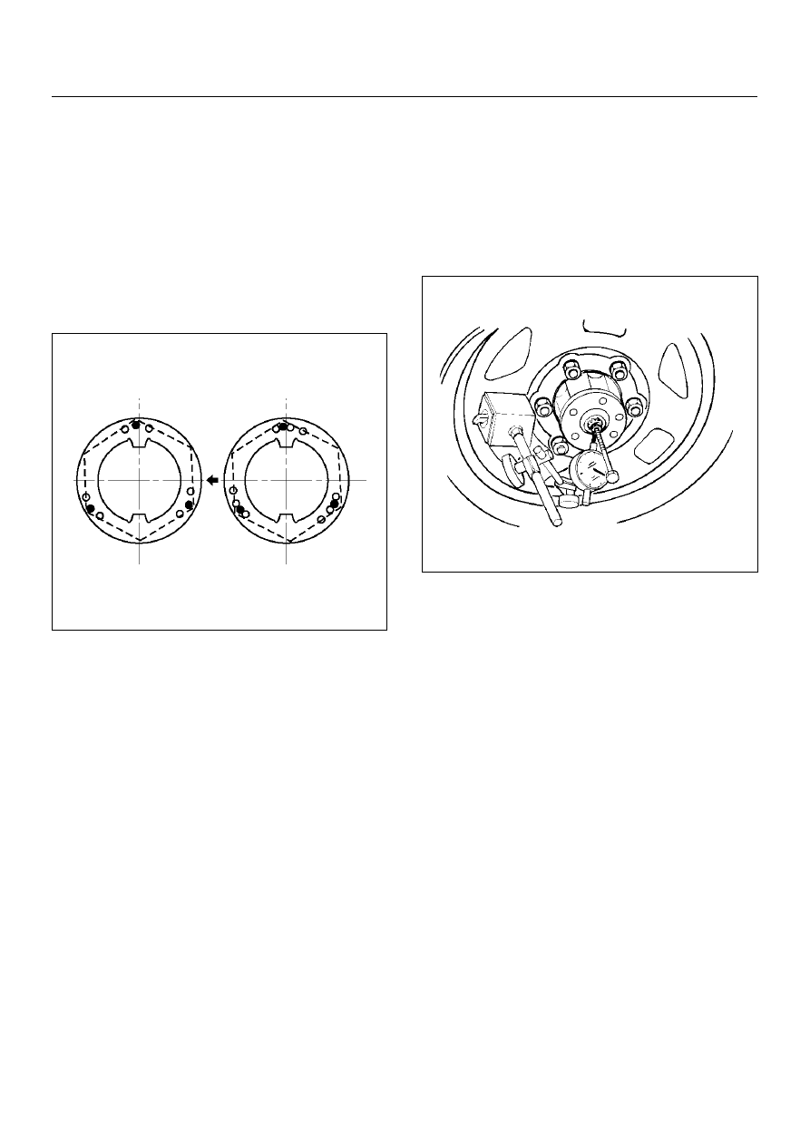
9. Install lock washer and lock screw in the following 

manner.

• Turn the side with larger diameter of the tapered 

bore to the vehicle outer side, then attach the 
washer.

• If the bolt holes in the lock plate are not aligned 

with the corresponding holes in the nut, reverse 
the lock plate.

• If the bolt holes are still out of alignment, turn in 

the nut just enough to obtain alignment.

• Screw is to be fastened tightly so its head may 

come lower than the surface of the washer.

411RS012

10. Apply adhesive (LOCTITE 515 or equivalent) to 

both joining flange faces then install hub flange.

11. Install snap ring and shim.

• Adjust the clearance between the free wheeling 

hub body and the snap ring.

Clearance: 0mm–0.3mm (0in–0.012in)

Shims Available: 0.2mm, 0.3mm, 0.5 mm, 1.0 mm 

(0.008in, 0.012in, 0.020in, 0.039in)

411RW002

12. Install hub cap.

13. Tighten the bolts to the specified torque.

Torque: 59N·m (6.0kg·m/43lbft)

4C–8

DRIVE SHAFT SYSTEM

Front Drive Shaft Joint

Front Drive Shaft Joints 
Replacement

• Refer to Front Drive Axle Assembly Replacement in 

this section, and refer to Front Hub and Disc Overhaul 
in Suspension section.

Front Hub Bearing Preload Check

Check the hub bearing preload at the wheel pin.

New bearing and New oil seal:

20 – 25N (2.0 – 2.5kg·m/4.4 – 5.5lb)

Used bearing and New oil seal:

12 – 18N (1.2 – 1.8kg·m/2.6 – 4.0lb)

411RS011

Inspection Of Shift On The Fly System Gear 
Oil

412RW035

1. Open filler plug and make sure that the oil up to the 

plug port.
If the oil is short, replenish with gear oil GL–5 grade.

2. Tighten the filler plug to specified torque.

Torque:78 N·m (8.0kg·m/58 lbft)

DRIVE SHAFT SYSTEM

4C–9

Front Axle Drive Shaft

Front Axle Drive Shaft and Associated Parts

412RX012

Legend

EndOFCallout

(1) Axle Case and  Differential
(2) Snap Ring
(3) Bearing
(4) Snap Ring
(5) Oil Seal
(6) Bracket
(7) Bolt
(8) Drive Shaft Joint Assembly
(9) DOJ Case

(10) Circlip
(11) Ball
(12) Snap Ring

(13) Ball Retainer
(14) Ball Guide
(15) Band
(16) Bellows
(17) Band
(18) Band
(19) Bellows
(20) Band
(21) BJ Shaft
(22) Dust Seal

4C–10

DRIVE SHAFT SYSTEM

Disassembly

NOTE:  For the left side, follow the same steps as right 
side.

1. Raise the hooked end of the band with a 

screwdriver or equivalent.

412RS009

2. Remove band(1).

3. Pry off circlip (1) with a screwdriver or equivalent.

412RS010

4. Remove drive shaft joint assembly.

5. Remove the six balls (1) with a screwdriver or 

equivalent.

412RS012

6. Using snap ring pliers, remove the snap ring (1) 

fastening the ball retainer to the center shaft.

412RS013


Content   ..  695  696  697  698   ..