Opel Frontera UE. Manual - part 695
4B–22
DRIVELINE CONTROL SYSTEM
4WD Control Unit
4WD Control Unit Associated Parts
412RW042
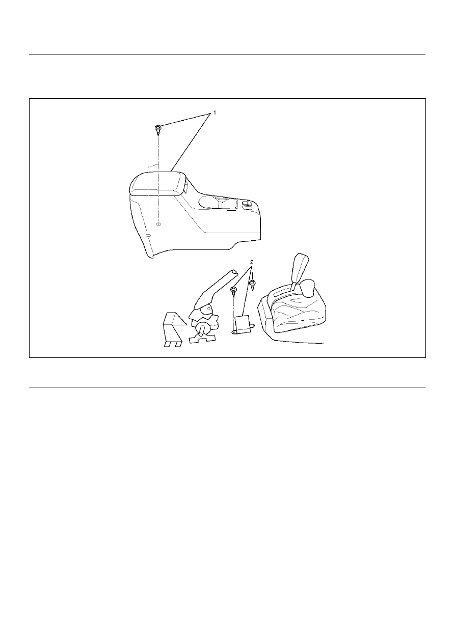
Legend
EndOFCallout
(1) Center Console Assembly
(2) 4WD Control Unit
|
|
|
4B–22 DRIVELINE CONTROL SYSTEM 4WD Control Unit 4WD Control Unit Associated Parts 412RW042 Legend EndOFCallout (1) Center Console Assembly (2) 4WD Control Unit |