Opel Frontera UE. Manual - part 602


  Index      Opel     Opel Frontera UE - service repair manual 1999-2001 year


Search            


Content   ..  600  601  602  603   ..


Opel Frontera UE. Manual - part 602


RESTRAINT CONTROL SYSTEM

9J1–53

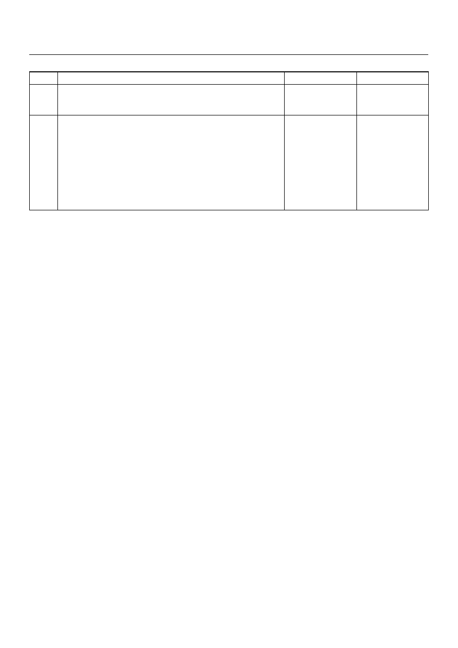
DTC 61 Warning Lamp Circuit Failure

Step

Action

Yes

No

1

Was the “SRS Diagnostic System Check" performed?

Go to Step 2

Go to the “SRS 

Diagnostic System 

Check."

2

1. Malfunctions within the “AIR BAG" warning lamp circuitry will 

set this diagnostic trouble code.

2. These malfunctions are addressed in the “SRS Diagnostic 

System Check" via Chart B and Chart C.

3. Failure to properly perform the “SRS Diagnostic System 

Check" may result in misdiagnosis.

4. Ignition switch “ON."

5. Clear SRS diagnostic trouble codes.

Is DTC 61 SET?

Ignition switch 

“OFF."

Go to Chart A.

Repeat the “SRS 

Diagnostic System 

Check."

9J1–54

RESTRAINT CONTROL SYSTEM

DTC 71  Internal SDM Fault

D09RX002

Circuit Description:

Diagnostic Trouble Code (DTC) 71 is an indication of a 
potential internal Sensing and Diagnostic Module 
(SDM) malfunction and will set if any of the  following 
conditions are detected:
1) Deployment or microprocessor energy reserve 
failure.
2) Electronically Erasable Programmable Read Only 
Memory failure. (EEPROM).
3) Random Only Memory failure. (ROM).
4) Random Access Memory failure. (RAM).
5) Calibration check sum failure.
6) Deployment switch faults.
7) Accelerometer fault.
8) Arming sensor fault.
9) Diagnostic current faults.
10) DTC 19
11) DTC 25
12) DTC 51

13) DTC 53

DTC Will Set When:

Any of the above indicated malfunctions are detected by 
the SDM.  The malfunctions described  above are 
tested mainly during “Continuous Monitoring" and some 
ones run each ignition cycle.

Action Taken:

SDM turns “ON" the “AIR BAG" warning lamp and sets 
a diagnostic trouble code.

DTC Will Clear When:

A scan tool “Clear Codes" commanded is received by 
the SDM.  Some of the indicated  malfunctions will only 
allow the “AIR BAG" warning lamp to go out.
But when DTC 19, 25, 51, 53 are also set, SDM is 
Replaced.

RESTRAINT CONTROL SYSTEM

9J1–55

DTC 71 Internal SDM Fault

WARNING:  DURING SERVICE PROCEDURES.  BE 
VERY CAREFUL WHEN HANDLING A SENSING AND 
DIAGNOSTIC MODULE (SDM).  NEVER STRIKE OR 
JAR THE SDM.  NEVER POWER UP THE SRS WHEN 
THE SDM IS NOT RIGIDLY  ATTACHED TO THE 
VEHICLE.  ALL SDM AND MOUNTING BRACKET 
FASTENERS MUST BE CAREFULLY TORQUED  
AND THE ARROW MUST BE POINTING TOWARD 
THE FRONT OF THE VEHICLE TO ENSURE PROPER 
OPERATION OF THE SRS. THE SDM COULD BE 
ACTIVATED WHEN POWERED WHILE NOT RIGIDLY 
ATTACHED TO THE VEHICLE WHICH COULD 
CAUSE DEPLOYMENT AND RESULT IN PERSONAL 

INJURY.

CAUTION:  When Diagnostic Trouble Code (DTC) 19 
or 25 or 51 or 53 has been set it is necessary to 
Replace the SDM. Setting DTC 19 and 25 or 51 or 53 
will also cause DTC 71 to set. When a scan tool 
“CLEAR CODES" command is issued and the 
malfunction is no longer present, DTC 51 or 53 and 
DTC 71 will remain current. Ensure that the short to 
voltage condition DTC 19, 25 is repaired prior to 
installing a Replacement SDM to avoid damaging 
the SDM.

Step

Action

Yes

No

1

Was the “SRS Diagnostic System Check" performed?

Go to Step 2

Go to the “SRS 

Diagnostic System 

Check."

2

Note SRS “Diagnostic System Check."
Is DTC 19 or 25 or 51 or 53 also set (current or history)? (Refer to 
notice above).

Go to DTC 19 if 

DTC 19 is set.

Go to DTC 25 if 

DTC 25 is set.

Go to DTC 51 if 

DTC 51 is set.

Go to DTC 53 if 

DTC 53 is set.

Ignition switch 

“OFF."

Replace SDM.

Repeat the 

“SRS 

Diagnostic 

System Check."

CRUISE CONTROL SYSTEM

10A–1

CONTROL SYSTEMS

CRUISE CONTROL SYSTEM

CONTENTS

Service Precaution......................................... 10A - 1
General Description ....................................... 10A - 2
Diagnosis ....................................................... 10A - 2

Brake Switch ................................................. 10A - 3

Removal and Installation ............................ 10A - 3
Adjustment.................................................. 10A - 3

Clutch Switch ................................................ 10A - 3

Removal and Installation ............................ 10A - 3
Adjustment.................................................. 10A - 3

Cruise Control Unit ........................................ 10A - 4

Removal ..................................................... 10A - 4
Installation .................................................. 10A - 4

Cruise Actuator ............................................. 10A - 5

Actuator Cable Diagram ............................. 10A - 5
Removal...................................................... 10A - 5
Installation................................................... 10A - 5
Adjustment.................................................. 10A - 6

Mode Switch.................................................. 10A - 6

Removal and Installation ............................ 10A - 6

Cruise Control Main Switch ........................... 10A - 6

Removal...................................................... 10A - 6
Installation................................................... 10A - 6

Cruise Control Switch (Combination Switch). 10A - 7

Removal and Installation ............................ 10A - 7

Service Precaution

WARNING:  THIS VEHICLE HAS A SUPPLEMENTAL
RESTRAINT SYSTEM (SRS).  REFER TO THE SRS
COMPONENT AND  WIRING LOCATION VIEW IN
ORDER TO DETERMINE WHETHER YOU ARE
PERFORMING SERVICE ON OR NEAR THE SRS
COMPONENTS  OR THE SRS WIRING.  WHEN YOU
ARE PERFORMING SERVICE ON OR NEAR THE
SRS COMPONENTS OR THE SRS WIRING, REFER
TO  THE SRS SERVICE INFORMATION.  FAILURE TO
FOLLOW WARNINGS COULD RESULT IN POSSIBLE
AIR BAG DEPLOYMENT, PERSONAL  INJURY, OR
OTHERWISE UNNEEDED SRS SYSTEM REPAIRS.

CAUTION:  Always use the correct fastener in the
proper location.  When you replace a fastener, use
ONLY the exact part  number for that application.
ISUZU will call out those fasteners that require a
replacement after removal.  ISUZU will also call out
the  fasteners that require thread lockers or thread
sealant.  UNLESS OTHERWISE SPECIFIED, do not
use supplemental coatings  (Paints, greases, or
other corrosion inhibitors) on threaded fasteners or
fastener joint interfaces.  Generally, such coatings
adversely  affect the fastener torque and the joint
clamping force, and may damage the fastener.
When you install fasteners, use the correct
tightening sequence and specifications.  Following
these instructions can help you avoid damage to
parts and systems.

SECTION


Content   ..  600  601  602  603   ..