Opel Frontera UE. Manual - part 601
RESTRAINT CONTROL SYSTEM
9J1–49
DTC 53 Deployment Commanded With Deployment Loop Fault Or Energy
Reserves Out Of Range
D09RX002
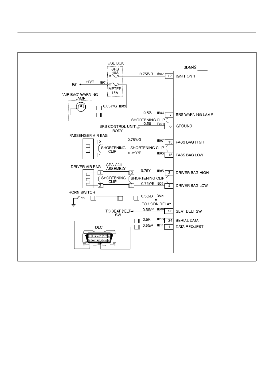
Circuit Description:
The Sensing and Diagnostic Module (SDM) contains a
sensing drive which converts vehicle velocity changes
to an electrical signal. The electrical signal generated
is processed by the SDM and then compared to a value
stored in memory. When the generated signal exceeds
the stored value, the SDM will cause current to flow
through the air bag assembly deploying the air bags.
Diagnostic Trouble Code (DTC) 53 is set accompanying
with DTC 51 when a deployment occurs while an air bag
assembly circuit fault is present that could possible
result in a no deployment situation in one or both air bag
assemblies.
DTC Will Set When:
The SDM detects a frontal crash, up to 30 degrees off
the centerline of the vehicle, of sufficient force to
warrant deployment of the air bags and an inflator circuit
fault is present.
Action Taken:
SDM turns “ON" the “AIR BAG" warning lamp records
“Crash Data", and sets a diagnostic trouble code.
DTC Will Clear When:
The SDM is replaced. If DTC 53 is set, one or more
DTCs will be set in addition to DTC 53. Malfunction(s)
setting DTC(s) (other than DTC 71) must be repaired so
that DTC(s) will not be set when a new SDM is
installed.