Opel Frontera UE. Manual - part 549


  Index      Opel     Opel Frontera UE - service repair manual 1999-2001 year


Search            


Content   ..  547  548  549  550   ..


Opel Frontera UE. Manual - part 549


8F–56

BODY STRUCTURE

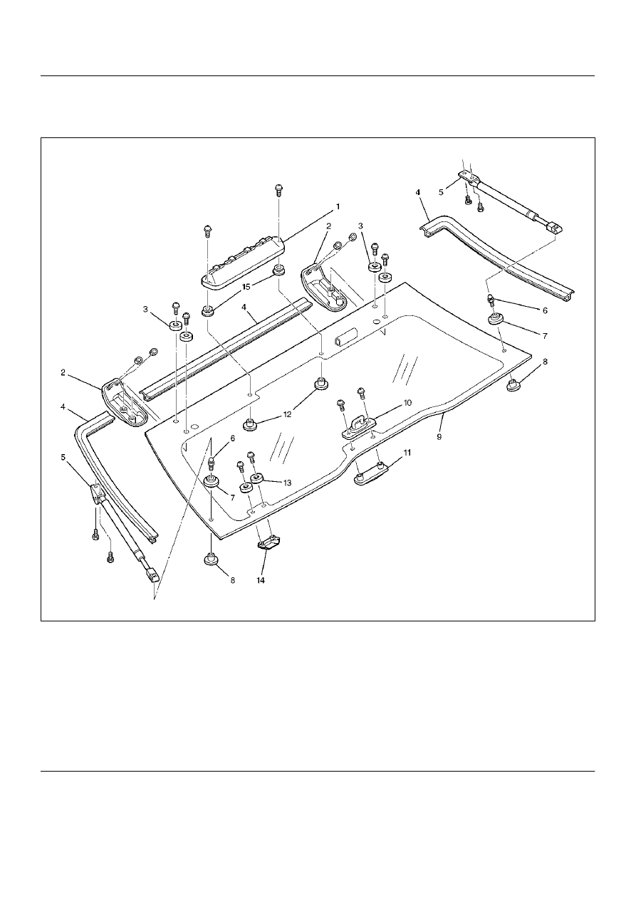
Rear Hatchgate (LWB)

Parts Location

682RW002

Legend

EndOFCallout

(1) High Mount Stoplight
(2) Hatchgate Hinge
(3) Hinge Collar
(4) Hatchgate Glass Seal
(5) Hatchgate Gas Stay
(6) Hatchgate Ball Stud
(7) Ball Stud Spacer
(8) Ball Stud Fastener

(9) Hatchgate Glass

(10) Hatchgate Striker
(11) Striker Fastener
(12) High Mount Stoplight Fastener
(13) Outside Handle Collar
(14) Outside Handle
(15) High Mount Stoplight Spacer

BODY STRUCTURE

8F–57

Removal

1. Disconnect the battery ground cable.

2. Disconnect the high mount stoplight and rear 

defogger harness connectors.

3. Remove the hatchgate ball stud (LH and RH).

• Remove gas stay fixing screw and pull up the gas 

stay assembly (3) from the ball stud by spreading 
the retainer (2) holding the ball stud at the end of 
the gas stay with screwdriver (1), etc.

683RW004

4. Remove the hatchgate hinge nuts from body side.

5. Remove the hatchgate glass.

• When pulling down the hatchgate glass, exercise 

special care so as not to damage it.
Hatchgate glass assembly is heavy and removal 
operation requires the two people.

6. Remove the two screws to remove hatchgate striker 

and fastener.

7. Remove the outside handle.

8. Remove the hinges.

9. Remove the high mount stoplight.

10. Remove the hatchgate finisher.

Installation

To install, follow the removal steps in the reverse order, 
noting the following points.

1. Attach the upper seal (1) to the hatchgate glass (2) 

indicated portion (3) so that the end of the glass 
contacts the bottom of the upper seal.

682RW003

2. When installing the hatchgate glass, first attach the 

hinge to the hatchgate glass. Align the stud of the 
hinge to the hole at body while supporting the 
hatchgate glass with two people at indicated 
positions (1), and then partially tighten the hinge to 
body nut (2).
After adjustment (refer to Adjustment in this section) 
is completed, fully tighten the nut, hinge to body nut.

• Hatchgate hinge assembly for left and right sides 

from each other.

682RW005

8F–58

BODY STRUCTURE

3. When installing gas stay assembly (1), first install 

the gas stay onto the rear quarter panel  with fixing 
screw (2) and fastener (3) and then attach the gas 
stay upper end to the ball stud by spreading  the 
retainer with screwdriver, etc. Gas stay assemblies 
for left and right sides differ from each other  (The 
letter (4) L(LH) or R(RH) is embossed on the gas 
stay assembly.)

683RW005

4. When installing hatchgate striker assembly, first 

partially tighten the fixing screw and close  the 
hatchgate and tailgate. Then fully tighten the fixing 
screw with the condition that the striker fits the 
hatchgate lock assembly at the tailgate.
Make sure that clearance exists between hatchgate 
striker and lock assembly.
After installation, again make sure that the striker 
fits the lock assembly properly.

5. Tighten the nuts; hinge to body (LH and RH)

Torque : 6 N·m (0.6 kg·m/52 lb in)

6. Tighten the screws; glass and hinge fix (LH and RH)

Torque : 6 N·m (0.6 kg·m/52 lb in)

NOTE:  When installing the hinge to the body, exercise 
special care not to damage the body paint surface.

7. Tighten the hatchgate striker fixing screws.

Torque : 6 N·m (0.6 kg·m/52 lb in)

BODY STRUCTURE

8F–59

Adjustment

• Hatchgate alignment is obtained by moving 

hatchgate hinges.

682RW004

Legend

EndOFCallout

(1) Hatchgate Striker
(2) Hatchgate Glass
(3) Tailgate Outer Panel
(4) Tailgate Inner Panel
(5) Trim Cover

(6) Hatchgate Lock Assembly
(7) Quarter Trim
(8) Hatchgate Glass Seal
(9) Quarter Outer Panel


Content   ..  547  548  549  550   ..