Content .. 1748 1749 1750 1751 ..
Opel Frontera UE. Manual - part 1750
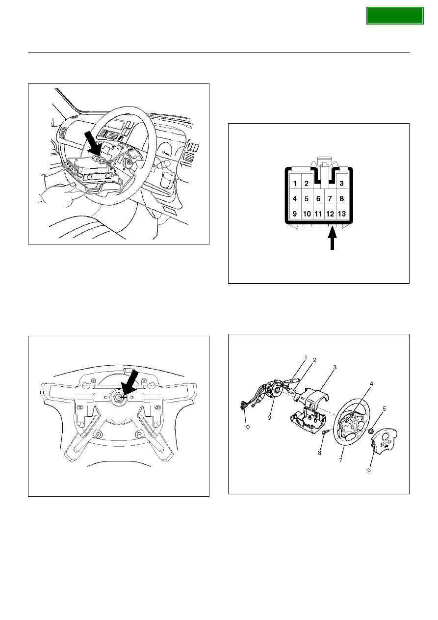
SUPPLEMENTAL RESTRAINT SYSTEM
9J–41
4. Disconnect the 2–pin yellow connector (2) and
remove air bag assembly.
827RX035
3. Disconnect horn lead connector (1).
4. Remove the steering wheel attachment nut (5).
5. Move the tires to the straight ahead position before
removing the steering wheel and remove wheel with
5–8521–0016–0.
6. Apply a setting mark (4) across the steering wheel
and shaft so parts can be reassembled in their
original position.
827RW063
7. Feed wiring though the wheel and remove wheel.
CAUTION: Never apply force to the steering wheel
in the direction of the shaft by using a hammer or
other impact tools in an attempt to remove the
steering wheel. The steering shaft is designed as an
energy absorbing unit.
8. Remove the steering lower cover.
9. Remove the driver knee bolster assembly.
10. Remove the steering column cover (3).
11. Disconnect the wiring harness connectors (10)
located at the base of steering column.
12. Disconnect the horn terminal NO.2 from connector
and remove the tape binding harness. (Refer to How
to Disconnect the horn terminal in this section.)
827RX029
13. Remove four bolts of combination switch assembly
(9) attached to steering lock and remove the
combination switch assembly (with SRS coil) from
steering shaft.
825RX047