Content .. 1726 1727 1728 1729 ..
Opel Frontera UE. Manual - part 1728
8H–16
SECURITY AND LOCKS
Keyless Entry System
General Description
This circuit consists of the keyless entry control unit, the
front door lock & power window switch (RH), the starter
switch, the dome light, the door switch and the tail gate
switch and possible to be locked/unlocked each door by
operation of transmitter. Basic function of system is as
follows.
Keyless Entry Control Unit
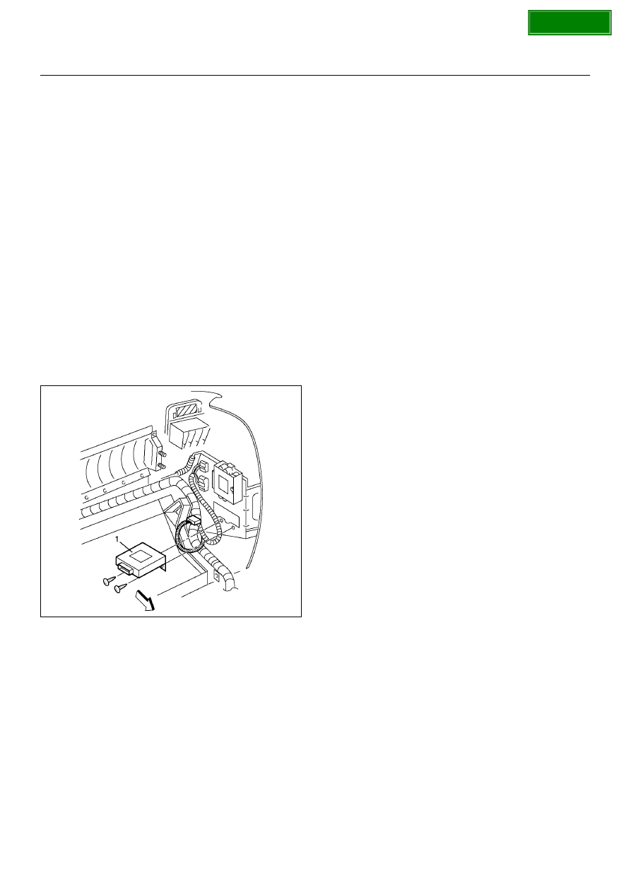
Removal
1. Disconnect the battery ground cable.
2. Remove the glove box.
• Refer to the Instrument Panel Assembly in Body
Structure section.
3. Remove the keyless entry control unit (1).
• Disconnect the connector.
• Remove two fixing screws.
826R100030
Installation
To install, follow the removal steps in the reverse order.
Keyless Entry Control Unit/
Transmitter Replacement
Keyless Entry Control Unit Replacement
1. Remove and install the control unit.
• Refer to Keyless Entry Control Unit in this section.
2. Register ID code.
• Refer to ID Code Registration in Wiring System
section.
3. Check that the keyless entry system works normally.
Transmitter Replacement
1. Prepare a new transmitter.
2. Regiter ID code.
• Refer to ID Code Registration in Wiring System
section.
3. Check that the keyless entry system works normally.
Transmitter Battery Replacement
1. Remove the cover.
• Remove the fixing screw.
2. Remove the battery.
3. Set the new battery into the transmitter.
4. Install the cover to the transmitter.
5. Check that the keyless entry system works normally.