Content .. 1645 1646 1647 1648 ..
Opel Frontera UE. Manual - part 1647
8D–18
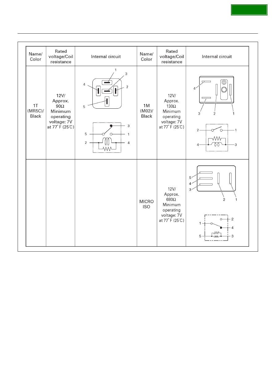
WIRING SYSTEM
Relay Specifications and Configurations
D08R100212
*
Relay contact shown in the wiring diagram indicates
condition before actuation.
|
|
|
Content .. 1645 1646 1647 1648 ..
8D–18 WIRING SYSTEM Relay Specifications and Configurations D08R100212 * Relay contact shown in the wiring diagram indicates condition before actuation. |