Opel Frontera UE. Manual - part 1646


  Index      Opel     Opel Frontera UE - service repair manual 1999-2001 year


Search            


Content   ..  1644  1645  1646  1647   ..


Opel Frontera UE. Manual - part 1646


8D–14

WIRING SYSTEM

Wiring – Wire Size
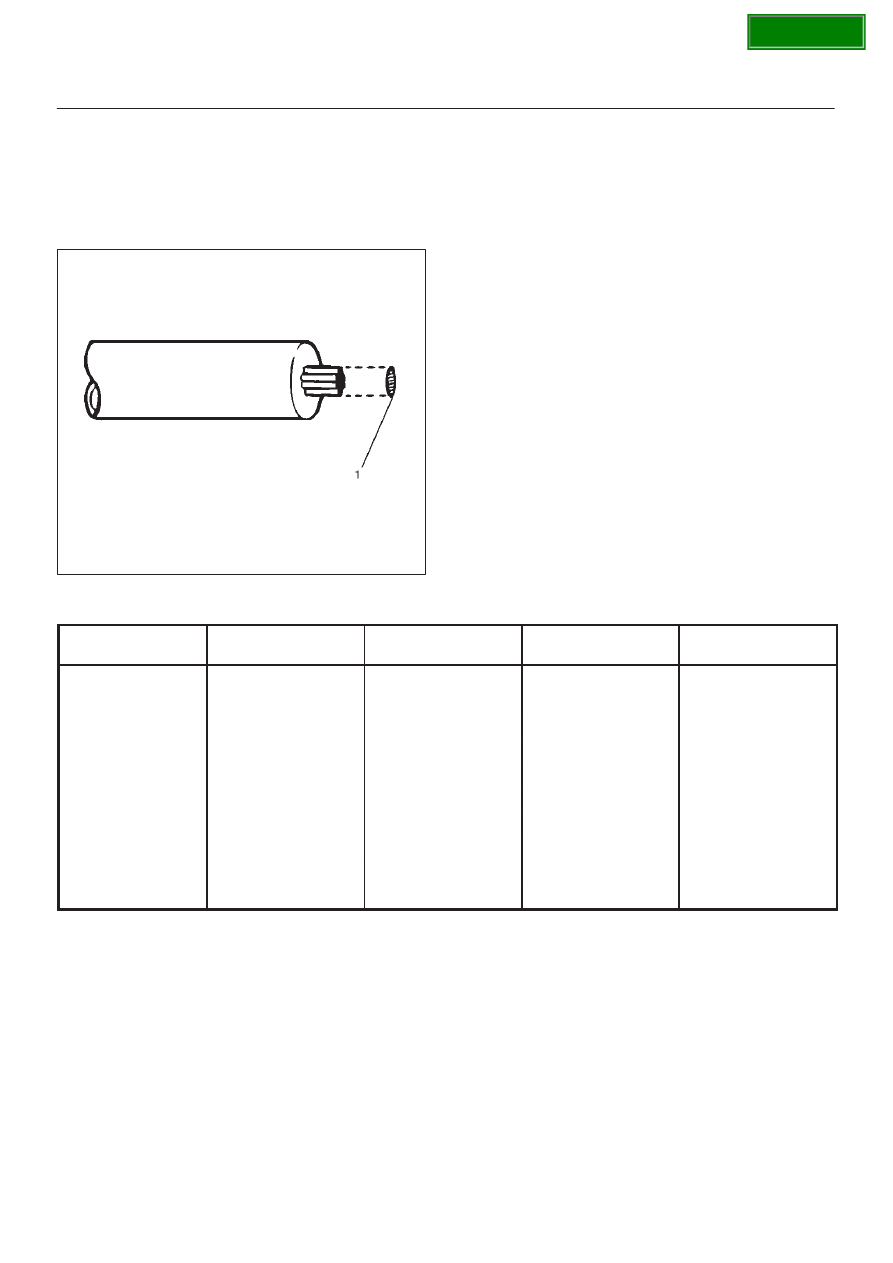
The size of wire used in a circuit is determined by the
amount of current (amperage), the length of the circuit,
and the voltage drop allowed. The following wire size and
load capacity, shown below, are specified by AWG
(American Wire Gauge) (Nominal size means
approximate cross sectional area (1).)

D08RW151

Wiring – Wire Size Table

Nominal size

Cross sectional area

(mm

@

)

Outside diameter

(mm)

Allowable current (A)

AWG size 

(cross reference)

0.3

0.372

1.5

9

22

0.5

0.563

1.7

12

20

0.85

0.885

1.9

16

18

1.25

1.287

2.2

21

16

2

2.091

2.7

28

14

3

3.296

3.6

37.5

12

5

5.227

4.4

53

10

8

7.952

5.5

67

8

15

13.36

7.0

75

6

20

20.61

8.2

97

4

SECTION

8D–15

WIRING SYSTEM

Fuse
Fuses are the most common form of circuit protection
used in vehicle wiring. A fuse is a thin piece of wire or strip
of metal encased in a glass it or plastic housing. It is wired
in series with the circuit in protects. When there is an
overload of current in a circuit, such as a short of a
ground, the metal strip is designed to burn out and
interrupt the flow of current. This prevents a surge of high
current from reaching and damaging other components in
the circuit.
Determine the cause of the overloaded before replacing
the fuse.
The replacement fuse must have the same amperage
specification as the original fuse.
Never replace a blown fuse with a fuse of a different
amperage specification.
Doing so can result in an electrical fire or other serious
circuit damage. A blown fuse is easily identified as shown
in the figure.

810RX001

SECTION

8D–16

WIRING SYSTEM

Fusible Link
The fusible link is primarily used to protect circuits where
high amounts of current flow and where it would not be
practical to use a fuse. For example, the starter circuit.
When a current overload occurs, the fusible link melts
open and interrupts the flow of current so as to prevent the
rest of the wiring harness from burning.
Determine the cause of the overload before replacing the
fusible link. the replacement fusible link must have the
same amperage specification as the original fusible link.
Never replace a blown fusible link with fusible link of a
different amperage specification. Doing so can result in
an electrical fire or other serious circuit damage.
A blown fusible link is easily identified as shown in the
figure.

D08RW154

Fusible Link Specifications

Type

Rating

Case Color

Maximum Circuit Current (A)

Connector

30A

Pink

15

Connector

40A

Green

20

Bolted

50A

Red

25

Bolted/Connector

60A

Yellow

30

Bolted

80A

Black

40

Bolted

100A

Blue

50

SECTION

8D–17

WIRING SYSTEM

Circuit Breaker
The circuit breaker is a protective device designed to
open the circuit when a current load is in excess of rated
breaker capacity. If there is a short or other type of
overload condition in the circuit, the excessive current will
open the circuit between the circuit breaker terminals.
The reset knob (1) pops out when the circuit is open. Push
the reset knob in place to restore the circuit after repairing
it.

D08RW155

Relay
Battery and load location may require that a switch be
placed some distance from either component. This
means a longer wire and a higher voltage drop (1).
The installation of a relay between the battery and the
load reduces the voltage drop (2).
Because the switch controls the relay, amperage through
the switch can be reduced.

D08RW156

SECTION


Content   ..  1644  1645  1646  1647   ..