Opel Frontera UE. Manual - part 1636


  Index      Opel     Opel Frontera UE - service repair manual 1999-2001 year


Search            


Content   ..  1634  1635  1636  1637   ..


Opel Frontera UE. Manual - part 1636


8A–18

LIGHTING SYSTEM

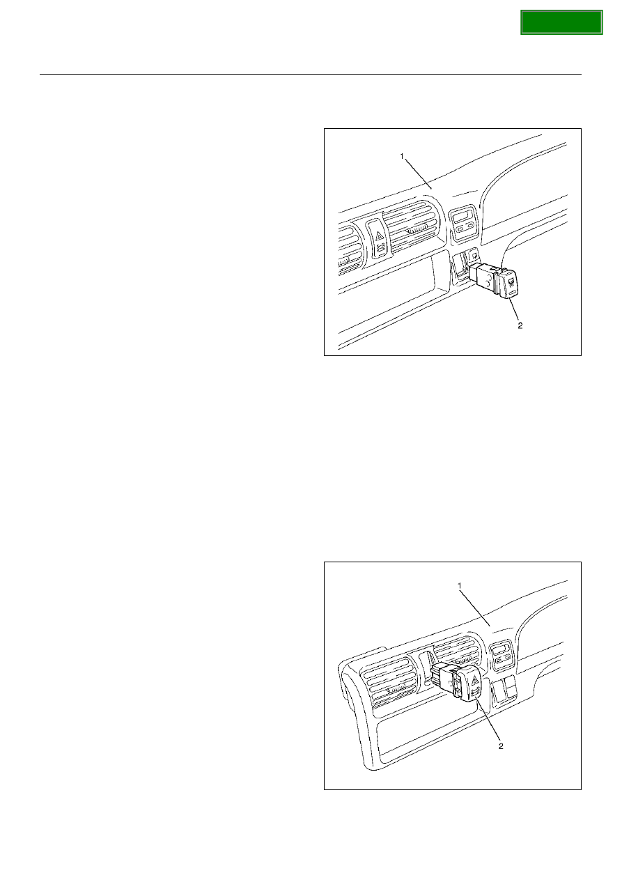
Rear Defogger Switch

Removal

1. Disconnect the battery ground cable.

2. Remove the meter cluster assembly (1).

• Refer to Instrument Panel Assembly in Body 

Structure section.

3. Remove the rear defogger switch (2).

• Disconnect the switch connector.

• Push the lock from the back side of the meter 

cluster assembly.

825RW280

Installation

To install, follow the removal steps in the reverse order.

Key Remind Switch (Starter Switch)

Removal and Installation

Refer to Lock Cylinder in Steering section.

Hazard Warning Light Switch

Removal

1. Disconnect the battery ground cable.

2. Remove the meter cluster assembly (1).

• Refer to Instrument Panel Assembly in Body 

Structure section.

3. Remove the hazard warning switch (2).

• Disconnect the switch connector.

• Push the lock from the back side of the meter 

cluster assembly.

825RW279

Installation

To install, follow the removal steps in the reverse order.

SECTION

LIGHTING SYSTEM

8A–19

Stoplight Switch

Removal and Installation

Refer to Stoplight Switch in Brake section.

4WD Switch

Removal

1. Disconnect the battery ground cable.

2. Remove the meter cluster assembly (1).

• Refer to Instrument Panel Assembly in Body 

Structure section.

3. Remove the 4WD switch (2).

• Disconnect the switch connector.

• Push the lock from the back side of the meter 

cluster assembly.

825RW275-1

Installation

To install, follow the removal steps in the reverse order.

Fog Light Switch

Removal

1. Disconnect the battery ground cable.

2. Remove the meter cluster assembly (1).

• Refer to Instrument Panel Assembly in Body 

Structure section.

3. Remove the fog light switch (2).

• Disconnect the switch connector.

• Push the lock from the back side of the meter 

cluster assembly.

825RW274

Installation

To install, follow the removal steps in the reverse order.

SECTION

8A–20

LIGHTING SYSTEM

TOD Switch

Removal

1. Disconnect the battery ground cable.

2. Remove the meter cluster Assembly (1).

• Refer to Instrument Panel Assembly in Body 

Structure section.

3. Remove the TOD switch (2).

• Disconnect the switchs (2) (3) (4) connectors.

• Push the lock from the back side of the meter 

cluster assembly.

825R100031

Installation

To install, follow the removal steps in the reverse order.

Cruise Main Switch

Removal

1. Disconnect the battery ground cable.

2. Remove the meter cluster assembly (1).

• Refer to Instrument Panel Assembly in Body 

Structure section.

3. Remove the cruise main switch (2).

• Disconnect the switch connector.

• Push the lock from the back side of the meter 

cluster assembly.

825R100032

Installation

To install, follow the removal steps in the reverse order.

SECTION

LIGHTING SYSTEM

8A–21

Power/Winter Switch

Removal

1. Disconnect the battery ground cable.

2. Remove the power/winter switch (1).

• Pull out the power/winter switch.

• Disconnect the switch connector.

825RY00076

Installation

To install, follow the removal steps in the reverse order.

Intelligent Suspension Switch

Removal

1. Disconnect the battery ground cable.

2. Remove the intelligent suspension switch (1).

• Pull out the intelligent suspension switch.

• Disconnect the switch connector.

825RY00077

Installation

To install, follow the removal steps in the reverse order.

SECTION


Content   ..  1634  1635  1636  1637   ..