Opel Frontera UE. Manual - part 1621


  Index      Opel     Opel Frontera UE - service repair manual 1999-2001 year


Search            


Content   ..  1619  1620  1621  1622   ..


Opel Frontera UE. Manual - part 1621


MANUAL TRANSMISSION

7B–33

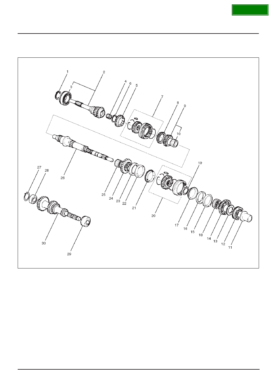
Top Gear Shaft, Main Gear Shaft, and Counter Gear Shaft (MUA)

Disassmebled View

226RS026

Legend

(1) Top Gear Shaft Snap Ring
(2) Top Gear Shaft
(3) Ball Bearing
(4) Needle Bearing
(5) Top Block Ring
(6) Mainshaft Snap Ring
(7) 3rd–4th Synchronizer Assembly
(8) 3rd Block Ring
(9) 3rd Gear

(10) Needle Bearing

(11) Needle Bearing Collar

(12) Mainshaft Ball Bearing
(13) 1st Gear Thrust Bearing
(14) 1st Gear
(15) 1st Inside Ring

(16) 1st Outside Ring
(17) 1st Block Ring
(18) Needle Bearing
(19) Clutch Hub Snap Ring
(20) 1st–2nd Synchronizer Assembly
(21) 2nd Block Ring
(22) 2nd Outside Ring
(23) 2nd Inside Ring
(24) 2nd Gear
(25) Needle Bearing
(26) Mainshaft
(27) Bearing Snap Ring
(28) Front Rollar Bearing
(29) Center Roller Bearing
(30) Counter Gear Shaft

SECTION

7B–34

MANUAL TRANSMISSION

Disassembly

1. Use a pair of snap ring pliers to remove the top gear

shaft snap ring(1).

2. Remove top gear shaft(2) with ball bearing(3).
3. Use a bench press and the bearing remover

5–8840–0015–0 to remove the ball bearing(3).

226RW216

4. Remove needle bearing(4) and top block ring(5),

mainshaft snap ring.

5. Use a pair of snap ring pliers to remove the mainshaft

snap ring(6).

226RS028

6. Use a bench press and the bearing remover

5–8840–0015–0 to remove the 3rd–4th synchronizer
assembly(7) as a set.
Disassemble the synchronizer assembly.

226RW217

Legend

(1) Springs
(2) Sleeve
(3) Clutch Hub
(4) Inserts

7. Remove 3rd block ring(8), 3rd gear(9), and needle

bearing(10).

8. Remove needle bearing collar(11).
9. Use a bench press and the bearing remover

5–8840–0015–0 to remove the 1st gear(14) together
with the mainshaft ball bearing(12) and 1st gear thrust
bearing(13).

226RW218

SECTION

MANUAL TRANSMISSION

7B–35

10. Disassemble 1st inside ring(15), 1st outside ring(16),

and 1st block ring(17).

11. Remove needle bearing(18).

12. Use a pair of snap ring pliers to remove the clutch hub

snap ring(19).

226RS031

13. Use a bench press and the bearing remover

5–8840–0015–0 to remove the 2nd gear(24) together
with 1st–2nd synchronizer assembly(20), 2nd block
ring(21), 2nd outside ring(22), and 2nd inside
ring(23).
Disassemble the synchronizer assembly.

226RW220

Legend

(1) Springs
(2) Sleeve
(3) Clutch Hub
(4) Inserts

14. Remove needle bearing(25) from mainshaft(26).
15. Remove bearing snap ring(27)

16. Use a bench press and the bearing remover

5–8840–0015–0 to remove the front roller
bearing(28).

226RW219

17. Remove center roller bearing(29) from counter gear

shaft(30).

Inspection and Repair

Make the necessary adjustments, repairs, and part
replacements if excessive wear or damage is discovered
during inspection.

Block Ring and Dog Teeth Clearance

D

Use a thickness gauge to measure the clearance
between the block ring and the dog teeth.

226RS035

If the measured value exceeds the specified limit, the
block ring must be replaced.

SECTION

7B–36

MANUAL TRANSMISSION

Block Ring and Dog Teeth Clearance

Standard

Limit

1.5 mm (0.059 in)

0.8 mm (0.032 in)

1st–2nd Synchronizer (3–CONE)

D

Use a thickness gauge to measure the clearance
between the block ring and the dog teeth.

226RS036

If the measured value exceeds the specified limit,the
1st–2nd synchronizer assembly must be replaced.

Block Ring and Dog Teeth Clearance

Standard

Limit

1.5 mm (0.059 in)

0.8 mm (0.032 in)

Block Ring and Insert Clearance

D

Use a vernier caliper or thickness gauge to measure
the clearance between the block ring and the insert.

226RS037

If the measured value exceeds the specified limit, the
block ring and the insert must be replaced.

Block and Insert Clearance


Standard

Limit

3rd–4th

3.46 – 3.74 mm

(0.136 – 0.147 in)

4.0 mm

(0.158 in)

1st–2nd

4.34 – 4.66 mm

(0.171 – 0.183 in)

4.9 mm

(0.193 in)

Rev–5th

3.59 – 3.91 mm

(0.141 – 0.154 in)

4.1 mm

(0.161 in)

Clutch Hub and Insert Clearance

D

Use a thickness gauge to measure the clearance
between the clutch hub and the insert.

226RS038

If the measured value exceeds the specified limit, the
clutch hub and the insert must be replaced.

Clutch Hub and Insert Clearance


Standard

Limit

3rd–4th

0.01 – 0.19 mm

(0.0004 – 0.0075 in)

0.3 mm

(0.012 in)

1st–2nd

0.09 – 0.31 mm

0.4 mm

Rev–5th

(0.0035 – 0.0122 in)

(0.016 in)

SECTION


Content   ..  1619  1620  1621  1622   ..