Content .. 1620 1621 1622 1623 ..
Opel Frontera UE. Manual - part 1622
MANUAL TRANSMISSION
7B–37
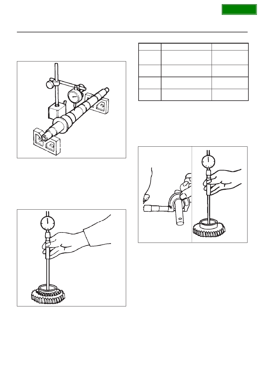
Mainshaft Run-out
D
Install the mainshaft to V-blocks.
D
Use a dial indicator to measure the mainshaft central
portion run-out.
226RS039
If the measured mainshaft run-out exceeds the
specified limit, the mainshaft must be replaced.
Mainshaft Run–out
Limit: 0.05 mm (0.0020 in)
Gear Inside Diameter
D
Use an inside dial indicator to measure the gear inside
diameter.
226RS040
If the measured value is less than the specified limit,
the gear must be replace.
Gear Inside Diameter
Standard
Limit
1st
45.000 – 45.013 mm
45.100 mm
3rd
(1.771 – 1.772 in)
(1.776 in)
2nd
52.000 – 52.013 mm
(2.047 – 2.048 in)
52.100 mm
(2.051 in)
Rev.
48.000 – 48.013 mm
(1.889 – 1.890 in)
48.100 mm
(1.894 in)
5th
32.000 – 32.013 mm
(1.259 – 1.260 in)
32.100 mm
(1.246 in)
Reverse Idler Gear and Idler Gear Shaft
Clearance
D
Use a micrometer to measure the idler gear shaft
diameter.
D
Use an inside dial indicator to measure the idler gear
inside diameter.
226RS041
D
Calculate the idler gear and idler gear shaft
clearance.
Idler gear inside diameter-idler gear shaft diameter =
idle gear and idler gear shaft clearance.
If the measured value exceeds the specified limit, the
idle gear and/or the idler gear shaft must be replaced.
Idler Gear and Idler Gear Shaft Clearance
Standard: 0.041–0.074 mm (0.016–0.0029 in)
Limit: 0.150 mm (0.0059 in)