Opel Frontera UE. Manual - part 1581


  Index      Opel     Opel Frontera UE - service repair manual 1999-2001 year


Search            


Content   ..  1579  1580  1581  1582   ..


Opel Frontera UE. Manual - part 1581


7A–46

AUTOMATIC TRANSMISSION (4L30–E)

Solenoid (Main Case Valve Body)

Removal

1. Raise the vehicle and support it on jack stands.
2. Disconnect battery ground cable.
3. Drain fluid.
4. Remove sixteen 10 mm screws, main case oil pan,

magnet, and gasket.

5. Remove three 13 mm screws, oil filter.
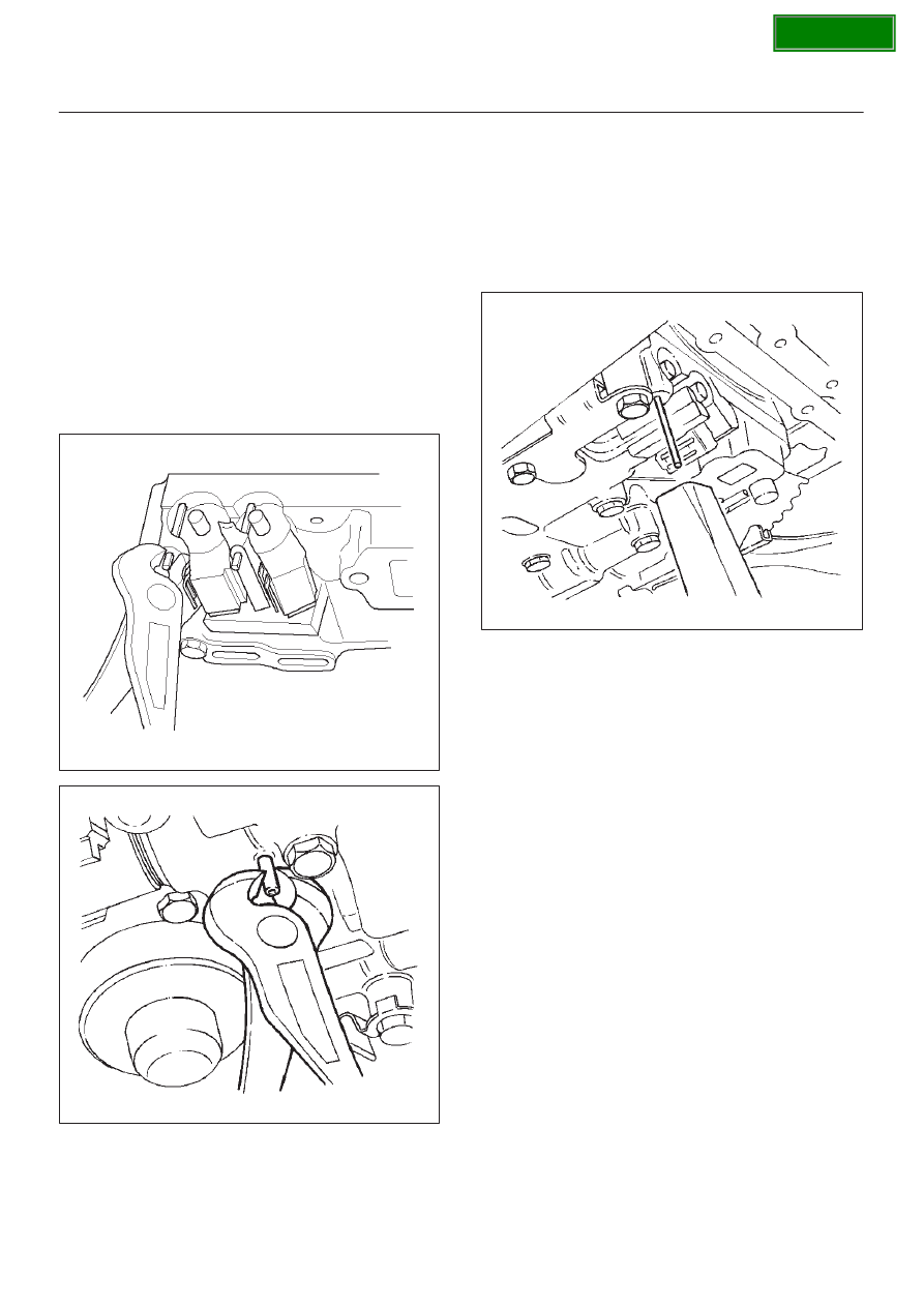
6. Disconnect wiring harness from band control

solenoid and shift solenoids. Pull only on connectors,
not on wiring harness.

7. Remove spring pin for shift solenoid A, shift solenoid

B, and band control solenoid respectively, using
suitable pliers taking care not to damage solenoids.

210RW010

244RW003

8. Remove shift solenoid A, shift solenoid B, band

control solenoid, and gaskets from main case valve
body. Do not pull on wiring harness. Remove
solenoids by grasping the metal tip.

Installation

1. Install shift solenoid A, shift solenoid B, band control

solenoid with new gaskets to main case valve body
respectively.

2. Carefully install spring pin with hammer to avoid

damage to valve body, etc.

243RW004

3. Connect wiring harness to solenoids.
4. Install oil filter with a new gasket and the three 13 mm

screws, tighten to the specified torque.

Torque: 20 N

m (15 lb ft)

5. Install magnet, main case oil pan with new gasket,

and sixteen 10 mm screws. Tighten the screws to the
specified torque.

Torque: 11 N

m (96 lb in)

6. Fill transmission through the overfill screw hole of oil

pan, using ATF DEXRON

–III. Refer to 

Changing

Transmission Fluid in this section.

7. Connect battery ground cable.

SECTION

7A–47

AUTOMATIC TRANSMISSION (4L30–E)

Solenoid (Adapter Case Valve Body)

Removal

1. Raise the vehicle and support it on jack stands.
2. Disconnect battery ground cable.
3. Drain fluid.
4. Remove adapter case oil pan twelve fixing 10 mm

screws, adapter case oil pan, and gasket.

NOTE: Oil pan still contains transmission fluid. Place a
large drain container under the oil pan and drain the fluid
carefully.

5. Disconnect wiring harness from force motor solenoid

and converter clutch solenoid. Pull only on
connectors, not on wiring harness.

6. Remove 11 mm bolt and converter clutch solenoid

with two O-rings.

210RW011

7. Remove 11 mm bolt, retainer, and force motor

solenoid.

210R100002

Installation

1. Install force motor solenoid, retainer, and 11 mm bolt

to adapter case valve body. Tighten the bolt to the
specified torque.

Torque: 10  N

m (87 lb in)

2. Install converter clutch solenoid with two O-rings, and

11 mm bolt to adapter case valve body. Tighten the
bolt to the specified torque.

Torque : 10 N

m (87 lb in)

3. Connect wiring harness assembly to solenoids.
4. Install adapter case oil pan, new gasket, and twelve

10 mm screws. Tighten the screws to the specified
torque.

Torque : 11 N

m (96 lb in)

5. Fill transmission through overfill screw hole oil pan,

using ATF DEXRON

–III. Refer to 

Changing

Transmission Fluid in this section.

6. Connect battery ground cable.

SECTION

7A–48

AUTOMATIC TRANSMISSION (4L30–E)

Valve Body Assembly (Main Case)

Removal

1. Raise the vehicle and support it on jack stands.
2. Disconnect battery ground cable.
3. Drain fluid.
4. Remove sixteen 10 mm screws, main case oil pan,

magnet and gasket.

5. Remove three 13 mm oil filter fixing screws, then

remove oil filter.

6. Remove two 13 mm manual detent fixing screws,

then remove roller and spring assembly.

7. Disconnect wiring harness from band control

solenoid and shift solenoids. Pull only on connectors,
not on wiring harness.

8. Remove four 13 mm servo cover fixing screws, then

remove servo cover and gasket.

9. Remove seven 13 mm valve body fixing screws.

10. Remove main case valve body with manual valve link

and transfer plate. Note the position of the link (long
end into valve, short end into range selector lever).

11. Remove transfer plate gasket from main case.

12. Remove two check balls from main case.

Installation

1. Install two check balls to main case.

244RW002

2. Inspect electrical 7 way connector and seal of main

case. Replace if necessary.

3. Use two J–25025–B guide pin to install main case.

D

Install valve body complete assembly and manual
valve link.

NOTE: Valve must be extended as the short end of
manual valve link is connected to the range selector lever.
Long end of link goes into valve.

4. Install seven 13 mm screws, and tighten them to the

specified torque.

Torque: 20 N

m (15 lb ft)

243RS008

5. Remove two guide pins from main case.
6. Install servo cover gasket, cover, and four 13 mm

screws. Tighten the screws to the specified torque.

Torque: 25 N

m (18 lb ft)

7. Connect wiring harness to band control and shift

solenoids.

8. Install roller and spring assembly to manual detent.

D

Install two 13 mm screws, and tighten them to the
specified torque.

Torque: 20 N

m (15 lb ft)

9. Install oil filter and three 13 mm screws. Tighten to the

specified torque.

Torque : 20 N

m (15 lb ft)

10. Install oil pan gasket, magnet, oil pan and sixteen 10

mm screws. Tighten the screws to the specified
torque.

Torque: 11 N

m (96 lb in)

11. Fill transmission through overfill screw hole of oil pan,

using ATF DEXRON

–III. Refer to 

Changing

Transmission Fluid in this section.

12. Connect battery ground cable.

SECTION

7A–49

AUTOMATIC TRANSMISSION (4L30–E)

Valve Body Assembly (Adapter Case)

Removal

1. Raise the vehicle and support it on jack stands.
2. Disconnect battery ground cable.
3. Drain fluid.
4. Remove twelve 10 mm adapter case oil pan fixing

screws, adapter case oil pan, and gasket. 

NOTE: Oil pan still contains transmission fluid. Place a
large drain container under the oil pan.
Drain the fluid carefully.

5. Disconnect wiring harness from force motor solenoid

and converter clutch solenoid. Pull only on
connectors, not on wiring harness. 

6. Remove seven 13 mm screws from adapter case

valve body assembly, then remove  transfer plate, two
gaskets, and adapter case valve body.

Installation

1. Inspect electrical 4 way connector and seal of adapter

case. Replace if necessary.

2. Install gasket, transfer plate, and gasket.
3. Install adapter case valve body and seven 13 mm

screws. Tighten the screws to the specified torque.

Torque: 20 N

m (15 lb ft)

4. Connect wiring harness assembly to converter clutch

solenoid and force motor.

5. Install oil pan gasket, oil pan, and twelve 10 mm

screws. Tighten the screws to the specified torque.

Torque: 11 N

m (96 lb in)

6. Fill transmission through the overfill screw hole of oil

pan, using ATF DEXRON

–III, Refer to 

Changing

Transmission Fluid in this section.

7. Connect battery ground cable.

SECTION


Content   ..  1579  1580  1581  1582   ..