Opel Frontera UE. Manual - part 156


  Index      Opel     Opel Frontera UE - service repair manual 1999-2001 year


Search            


Content   ..  154  155  156  157   ..


Opel Frontera UE. Manual - part 156


6A–48

ENGINE MECHANICAL (X22SE 2.2L)

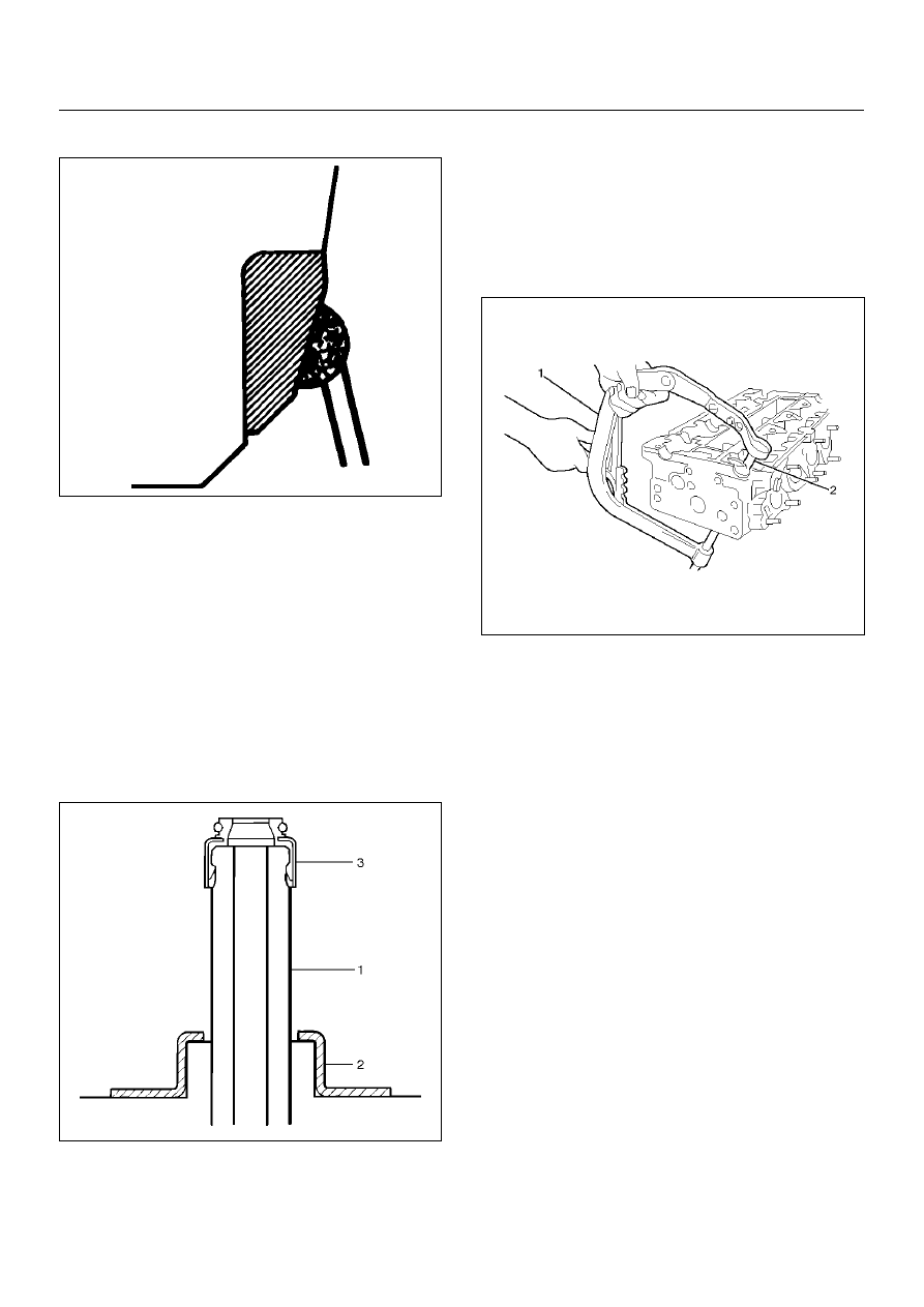
3. Strike the rod and pull it out.

014RS015

4. Carefully clean the valve seat press–fit section on 

the cylinder head side.

5. Heat the press–fit section with steam or some other 

means to cause expansion. Cool the valve seat with 
dry ice or some other means.

6. Insert the press–fit section into the valve seat 

horizontally.

7. Lap the valve and the seat.

Reassembly

1. Install oil controller (3) and spring lower seat (2). 

Using oil controller replacer 5–8840–2663–0, drive 
in a new oil controller.

014RS019

2. Install valve to valve guide. Before install valve guide 

apply engine oil to the outside of the valve stem.

3. Install valve spring to cylinder head. Attach the valve 

spring to the lower spring seat.

4. Install lower valve spring seat, valve spring and 

upper valve spring seat then put split collars on the 
upper spring seat, using 5–8840–2546–0 valve 
spring compressor for install the split collars.

011RW014

5. Install tappet.

6. Install camshaft assembly.

• Refer to installation procedure for Camshaft in 

this manual.

ENGINE MECHANICAL (X22SE 2.2L)

6A–49

Camshaft

Camshaft and Associated Parts

011RW023

Legend

EndOFCallout

Disassembly

1. Remove fixing bolt (1) for camshaft pulley (2).

2. Remove oil seal (3).

014RW035

(1) Camshaft Pulley Fixing Bolt
(2) Camshaft Pulley
(3) Oil Seal
(4) Camshaft Bracket

(5) Camshaft Bracket Fixing Bolt
(6) Camshaft Assembly Exhaust
(7) Camshaft Assembly Intake

6A–50

ENGINE MECHANICAL (X22SE 2.2L)

3. Remove oil seal (3).

4. Remove twenty fixing bolts (5) from inlet and 

exhaust camshaft bracket, then camshaft brackets 
(4).

011RW015

5. Remove camshaft assembly (6), (7).

Reassembly

1. Install camshaft drive gear assembly and tighten 

three bolts to specified torque.

Torque: 50 N·m (5.1Kg·m/37lbft) + 60

°°°°

 + 15

°°°°

2. Install camshaft assembly and camshaft brackets, 

tighten twenty bolts on one side bank to the 
specified torque.

1. Apply engine oil to camshaft journal and bearing 

surface of camshaft bracket.

2. Align timing mark on intake camshaft and 

exhaust camshaft to timing mark on camshaft 
drive gear (one dot).

3. Tighten twenty bolts on numerical order one 

side bank shown in the illustration.

Torque: 8 N·m (0.8Kg·m/6lbft)

4. If it required to replace oil seal of camshaft drive 

gear, use 5–8840–2658–0 for install the oil seal.

5. Tighten bolt for camshaft drive gear assembly 

pulley to the specified torque.

Torque: 50 N·m (5.1Kg·m/37lbft) + 60

°°°°

 + 15

°°°°

014RW036

ENGINE MECHANICAL (X22SE 2.2L)

6A–51

Crankshaft

Crankshaft and Associated Parts

015RW008

Legend

EndOFCallout

Disassembly

1. Remove cylinder head assembly (1). Refer to 

“Cylinder head" in this manual.

2. Remove oil pan (3).

CAUTION:  Take care not to damage or deform the 
sealing flange surface of crankcase.

3. Remove oil pan support (4).

4. Remove oil strainer (5).

5. Remove oil pump assembly (5).

6. Balance unit assembly.

7. Remove piston and connecting rod assembly (7). 

Refer to “Piston, Piston Ring and Connecting Rod" 
in this manual.

(1) Cylinder Head Assembly
(2) Oil Pump Assembly
(3) Pan
(4) Pan Support
(5) Oil Strainer

(6) Balance Unit Assembly
(7) Piston and Connecting Rod Assembly
(8) Main Bearing Cap
(9) Crankshaft

(10) Cylinder Block Assembly


Content   ..  154  155  156  157   ..