Opel Frontera UE. Manual - part 1366


  Index      Opel     Opel Frontera UE - service repair manual 1999-2001 year


Search            


Content   ..  1364  1365  1366  1367   ..


Opel Frontera UE. Manual - part 1366


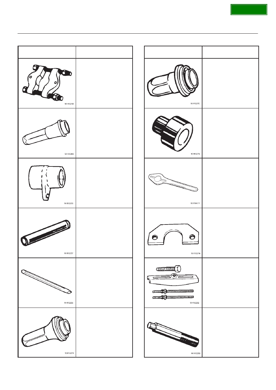
4D1–40 TRANSFER CASE

Special Tools

ILLUSTRATION

PART NO.

PART NAME

5–8840–0015–0

Bearing

remover/installer

5–8840–2279–0

Transfer case oil seal

installer

5–8840–2156–0

Mainshaft nut wrench

5–8840–2159–0

Rear output shaft and

bearing installer

5–8840–2293–0

Punch; end nut

5–8840–2281–0

Front output shaft oil

seal installer

ILLUSTRATION

PART NO.

PART NAME

5–8840–2292–0

Rear oil seal installer

5–8840–2192–1

Bearing installer adapter

5–8840–0133–0

Flange holder

5–8840–2155–0

Mainshaft end bearing

remover

5–8840–2027–0

Puller

5–8840–0007–0

Driver handle

SECTION

TRANSFER CASE 4D1–41

ILLUSTRATION

PART NO.

PART NAME

5–8840–2193–0

Transfer case oil seal

installer

SECTION

4D2–1

TRANSFER CASE (TOD)

FRONTERA

DRIVELINE/AXLE

TRANSFER CASE (TOD)

CONTENTS

Service Precaution

4D2–1

. . . . . . . . . . . . . . . . . . . . . . 

General Description

4D2–2

. . . . . . . . . . . . . . . . . . . . . 

Removal and Installation of Tfansfer Case
 Assembly

4D2–3

. . . . . . . . . . . . . . . . . . . . . . . . . . . . . . 

Removal

4D2–4

. . . . . . . . . . . . . . . . . . . . . . . . . . . . . . . 

Installation

4D2–4

. . . . . . . . . . . . . . . . . . . . . . . . . . . . . 

Transfer Rear Oil Seal

4D2–6

. . . . . . . . . . . . . . . . . . . 

Removal

4D2–6

. . . . . . . . . . . . . . . . . . . . . . . . . . . . . 

Installation

4D2–6

. . . . . . . . . . . . . . . . . . . . . . . . . . . . 

TOD Control Unit

4D2–8

. . . . . . . . . . . . . . . . . . . . . . . . 

Removal

4D2–8

. . . . . . . . . . . . . . . . . . . . . . . . . . . . . 

Installation

4D2–8

. . . . . . . . . . . . . . . . . . . . . . . . . . . . 

Unit Repair

4D2–9

. . . . . . . . . . . . . . . . . . . . . . . . . . . . . 

Disassembly and Reassembly of Major
 Components

4D2–9

. . . . . . . . . . . . . . . . . . . . . . . . . 

Disassembly

4D2–10

. . . . . . . . . . . . . . . . . . . . . . . . . . 

Reassembly

4D2–10

. . . . . . . . . . . . . . . . . . . . . . . . . . 

Transfer Cover Assembly

4D2–13

. . . . . . . . . . . . . . . 

Disassembly

4D2–13

. . . . . . . . . . . . . . . . . . . . . . . . . . 

Inspection and Repair

4D2–14

. . . . . . . . . . . . . . . . . . 

Reassembly

4D2–15

. . . . . . . . . . . . . . . . . . . . . . . . . . 

Clutch Pack and Clutch Cam
 (Transfer Case Assembly)

4D2–16

. . . . . . . . . . . . . . 

Disassembly

4D2–16

. . . . . . . . . . . . . . . . . . . . . . . . . . 

Reassembly

4D2–18

. . . . . . . . . . . . . . . . . . . . . . . . . . 

Chain, Sprocket and Mechanical Lock
 (Transfer Case Assembly)

4D2–20

. . . . . . . . . . . . . . 

Disassembly

4D2–21

. . . . . . . . . . . . . . . . . . . . . . . . . . 

Reassembly

4D2–22

. . . . . . . . . . . . . . . . . . . . . . . . . . 

Transfer Case Assembly

4D2–24

. . . . . . . . . . . . . . . 

Disassembly

4D2–24

. . . . . . . . . . . . . . . . . . . . . . . . . . 

Reassembly

4D2–26

. . . . . . . . . . . . . . . . . . . . . . . . . . 

Inspection and Repair
 (Transfer Case Assembly)

4D2–28

. . . . . . . . . . . . . . 

Main Data and Specification

4D2–32

. . . . . . . . . . . . . . 

General Specification

4D2–32

. . . . . . . . . . . . . . . . . . 

Torque Specifications

4D2–33

. . . . . . . . . . . . . . . . . . 

Special Tools

4D2–36

. . . . . . . . . . . . . . . . . . . . . . . . . . 

Service Precaution

WARNING: THIS VEHICLE HAS A SUPPLEMENTAL
RESTRAINT SYSTEM (SRS). REFER TO THE SRS
COMPONENT AND WIRING LOCATION VIEW IN
ORDER TO DETERMINE WHETHER YOU ARE
PERFORMING SERVICE ON OR NEAR THE SRS
COMPONENTS OR THE SRS WIRING. WHEN YOU
ARE PERFORMING SERVICE ON OR NEAR THE SRS
COMPONENTS OR THE SRS WIRING, REFER TO
THE SRS SERVICE INFORMATION. FAILURE TO
FOLLOW WARNINGS COULD RESULT IN POSSIBLE
AIR BAG DEPLOYMENT, PERSONAL INJURY, OR
OTHERWISE UNNEEDED SRS SYSTEM REPAIRS.

CAUTION: Always use the correct fastener in the
proper location. When you replace a fastener, use
ONLY the exact part number for that application.
ISUZU will call out those fasteners that require a
replacement after removal. ISUZU will also call out
the fasteners that require thread lockers or thread
sealant. UNLESS OTHERWISE SPECIFIED, do not
use supplemental coatings (Paints, greases, or other
corrosion inhibitors) on threaded fasteners or
fastener joint interfaces. Generally, such coatings
adversely affect the fastener torque and the joint
clamping force, and may damage the fastener. When
you install fasteners, use the correct tightening
sequence and specifications. Following these
instructions can help you avoid damage to parts and
systems.

SECTION

4D2–2

TRANSFER CASE (TOD)

General Description

A04R200003

The Torque-On-Demand (TOD) is an
electronically-controlled torque-split 4-wheel drive
system with the following features.

Shifting Between High and Low Ranges

The shifting mechanism consists of the cam and shaft rail
assembly, the high/low shift motor and the encoder. The
encoder is built-in to the motor.
The encoder senses high/low range shift motor rotation
position and sends this data to the TOD control unit.
Based on this data, the TOD control unit adjusts motor
rotation speed or stops the motor.
The shifting between the high and low ranges using the
TOD switch only is possible. The vehicle must be stopped
or nearly stopped (vehicle speed less than 2 km/h (1.2
mph) and engine speed less than 1,500 rpm), the
automatic transmission selector level must be in the
neutral (N) position, and the brakes must be applied.

Electronically-controlled Wet-type Multiple
Disc Clutch

The clutch automatically provides the optimum drive
power to the front wheels of the vehicle in response to
varying road surface conditions when the vehicle is
operated in the TOD mode. The delivered power ranges
from 0% to 100% of power train output. Superior
operational stability is maintained over a wide range of
operating conditions.

Front Output Drive

Front output drive is provided by a chain. This reduces the
loud noise associated with 4-wheel drive operation.

Oil Pump Lubrication

An oil pump is used to lubricate the transfer. This ensures
stable multiple-disc clutch operation and maintains the
lubricating oil at a constant temperature.

SECTION


Content   ..  1364  1365  1366  1367   ..