Opel Frontera UE. Manual - part 1353


  Index      Opel     Opel Frontera UE - service repair manual 1999-2001 year


Search            


Content   ..  1351  1352  1353  1354   ..


Opel Frontera UE. Manual - part 1353


4C–34

DRIVE SHAFT SYSTEM

Preload of the universal joint

Preload should be 0 to 24.9 kg(0 to11.3 lb).  Joints 
should rotate smoothly and freely and should exhibit no 
rough or ratchety movement.

401RW085

Boot

Check the boot for crack or damage. If necessary, 
replace the boot.
If abnormal condition are found on the boot, inspect the 
grease for mixing of foreign material.
If the grease is good condition, and slip joint works well, 
replace the boot, replenish grease, and reassemble the 
slip joint.
If the foreign material is found in the grease, check the 
spline for wear and damage.

Universal Joint Reassembly

1. Install spider to flange yoke. Be sure to install the 

spider by aligning the setting marks made during 
disassembly.

2. Pack the four grease cavities of the spider with a 

high quality, extreme pressure N.L.G.I. Grade 2 
grease.  Do not add additional grease to the bearing 
cup assembly.

3. Move one end of the spider to cause a trunnion to 

project through the spider hole beyond the outer 
machined face of the yoke lug.  Place a bearing over 
the trunnion diameter and align it to the spider hole.  
Using an arbor press, hold the trunnion in alignment 
with the spider hole and place a solid plug on the 
upper bearing.  Press the bearing into the spider 
hole enough to install a snap ring.

401RW020

4. Install a snap ring.

Be sure the snap rings are properly seated in the 
grooves.

5. Repeat steps 3 and 4 to install the opposite bearing.  

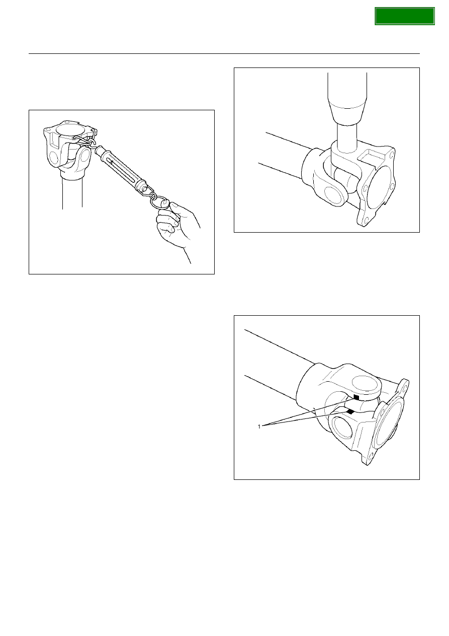
If the joint is stiff, strike the yoke ears with a soft 
hammer to seat needle bearings.

6. Align setting marks (1) and join the yokes.

401RW018

7. Install snap ring.

SECTION

DRIVE SHAFT SYSTEM

4C–35

Slip Joint Reassembly

401RW032

Legend

EndOFCallout

1. Apply grease evenly to both the female and male 

splines.

2. Apply a small amount of grease by finger to the 

outer lips of the boot.

3. Slide the boot (smaller diameter side) onto the 

spline yoke shaft being careful not to damage the 
spline coating or boot.

4. Insert the spline yoke shaft into the tube assembly 

being careful to maintain proper phasing.  The 
spider holes should be in line and as per originally 
marked prior to disassembly.

5. Position boot onto tube and yoke shaft in final 

position over boot grooves.

6. Attach boot clamps and secure using pliers.

7. Be sure clamp is properly seated and secure.

CAUTION:  Use new clamp which is the same parts 
as original. Do not use other clamp to avoid bad 
balancing of shaft or the grease leakage.

(1) Spline Yoke shaft
(2) Clamp
(3) Boot

(4) Clamp
(5) Tube Assembly

SECTION

4C–36

DRIVE SHAFT SYSTEM

With TOD (Torque On Demand 4

××××

4)

401R100006

Legend

EndOFCallout

Constant Velocity Joint

LJ and BJ constant velocity joints are unremovable 
types. Check the joint for play and the boot for damage, 
wear, and leak of grease. If abnormality is found, 
replace propeller shaft as an assembly.

Play in Constant Velocity Joint

Fix the shaft in a vise throrgh pieces of wood, and try to 
move the joint vertically, right and left, and back and 
forth to make sure of smooth motions and no 
remarkable play.

401RW050

401R100007

Boot of Constant Velocity Joint

Check the boot (2) for crack, damage and grease leak, 
and the boot band (1) for loosening and damage. Check 
the both sides of the joint and make sure that there is no 
leak of grease from the cover press-in parts(3).

401RW048

(1) LJ Constant Velocity Joint
(2) BJ Constant Velocity Joint

SECTION

DRIVE SHAFT SYSTEM

4C–37

401R100008

Front Axle Flange Run-out

1. Set a dial gage at right angle near the outer 

circumference of the flange face and check the 
run-out of the flange face.

Limit:0.15mm (0.006in)

401RW046

2. Set a dial gage at right angle near the inner 

circumference and check the run-out of the flange.

Limit:0.15 mm (0.006in)

401RW045

3. If vibration is felt during the 4H AUTO drive, 

disconnct the propeller shaft at the front axle. 
Reinstall the propeller shaft at 60

°

, 120

°

, 180

°

, 240

°

and  300

°

 and conduct test drive in each position 

and check if there is vibration.

401R100009

SECTION


Content   ..  1351  1352  1353  1354   ..