Opel Frontera UE. Manual - part 1352


  Index      Opel     Opel Frontera UE - service repair manual 1999-2001 year


Search            


Content   ..  1350  1351  1352  1353   ..


Opel Frontera UE. Manual - part 1352


4C–30

DRIVE SHAFT SYSTEM

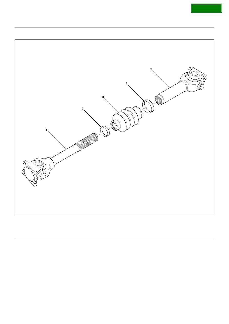
Slip Joint Disassembly

401RW032

Legend

EndOFCallout

1. Lay the shaft horizontally on a bench and secure.

2. Indicate the original assembled position (1) by 

marking the phasing of the shaft prior to 
disassembly.

(1) Spline Yoke Assembly
(2) Clamp
(3) Boot

(4) Clamp
(5) Tube Assembly

SECTION

DRIVE SHAFT SYSTEM

4C–31

401RW037

3. Using the flat blade of a screwdriver, pry the loose 

end of the boot clamp upwards and away from the 
propeller shaft boot.  Be careful not to damage the 
boot.

4. When boot clamps becomes loose, remove by 

hand.

5. Repeat for the other boot clamp.

6. Remove the spline yoke assembly from the tube 

assembly, by securing the boot with one hand and 
pulling on the spline yoke.

7. Remove the boot from the tube assembly.

Universal Joint Disassembly

401RW031

Legend

EndOFCallout

(1) Flange Yoke
(2) Snap Ring

(3) Spider
(4) Needle Roller Bearing

SECTION

4C–32

DRIVE SHAFT SYSTEM

1. Using a soft drift, tap the outside of the bearing cup 

assembly to loosen snap ring.  Tap bearing only 
hard enough to break assembly away from snap 
ring.
Remove snap ring from yoke.  Turn joint over, tap 
bearing away from snap ring, then remove opposite 
snap ring.
Apply alignment marks (1) on the yokes of the 
universal joint,  then remove snap ring.

401RW018

2. Set the yoke in the arbor press with a piece of tube 

stock beneath it.
Place a solid plug on the upper bearing assembly 
and press it through to release the lower bearing 
assembly.

401RW020

3. If the bearing assembly will not pull out by hand 

after pressing, tap the base of the lug near the 
bearing assembly to dislodge it.

4. To remove the opposite bearing, turn the yoke over 

and straighten the spider in the open hole.  Then 
carefully press on the end of the spider so the 
remaining bearing moves straight out of the bearing 
spider hole.  If the spider or bearing are cocked, the 
bearing will score the walls of the spider hole and 
ruin the yoke. 

5. Repeat this procedure on the remaining bearing to 

remove the spider from the yoke.

6. Make sure of proper position for reinstallation by 

applying setting marks, then remove spider .

Inspection and Repair

Make necessary correction or parts replacement if 
wear, damage, corrosion or any other abnormal 
condition is found through inspection.

NOTE:  When any part of the journal assembly (spider, 
needle roller bearing) requires replacement, be sure to 
replace the entire assembly.
Check the following parts for wear, damage, noise or 
any other abnormal conditions.

1. Spider

2. Needle roller bearing

3. Yoke

4. Flange

5. Boot

SECTION

DRIVE SHAFT SYSTEM

4C–33

Spider pin for wear

Spider pin should be smooth and free from fretting or 
galling.  Visible signs of needle presence is normal, but 
wear should not be felt.

401RW038

Propeller shaft runout

Support the propeller shaft on V-blocks (2) and check 
for runout by holding the probe of a dial indicator (1) in 
contact with the shaft.

Static runout limit:

0.13mm (0.005in)

TIR on the neck of the slip tube shaft (with a 
boot).

0.25mm (0.010in)

TIR on the ends of the tubing 3 inch from the 
welds.

0.38mm (0.015in)

TIR at the linear center of the tube.

0.38mm (0.015in)

TIR for the full length of tube with 30" or less of 
tubing.

(TIR : Total Indicator Reading)

401RS027

Spline

The nylon-coated spline should be free from nicks and 
dings and the underlying steel spline should not be 
visible.
After cleaning the nylon coating spline, the coating 
should exhibit only a slight indication of wear.
Grease volume is approximately 10 grams of grease in 
total.  Grease should be evenly applied to both the 
female and  the male slip splines using a small brush.  
After assembly of the slip joint, the sliding joint should 
be fully worked from the full collapsed to the full 
extended position.

Play in the universal joint

Limit:Less than0.15mm (0.006 in)

401RW023

SECTION


Content   ..  1350  1351  1352  1353   ..