Opel Frontera UE. Manual - part 1274


  Index      Opel     Opel Frontera UE - service repair manual 1999-2001 year


Search            


Content   ..  1272  1273  1274  1275   ..


Opel Frontera UE. Manual - part 1274


3C–18

FRONT SUSPENSION

Lower Control Arm

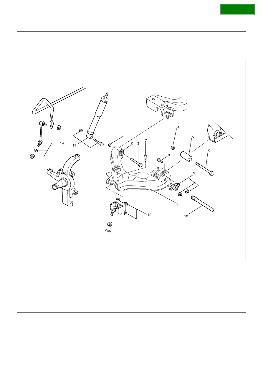
Lower Control Arm and Associated Parts

450R100005

Legend

EndOFCallout

Removal

1. Raise the vehicle and support the frame with 

suitable safety stands.

2. Remove wheel and tire assembly. Refer to 

Wheel in 

this section

.

3. Remove the tie-rod end from the knuckle. Refer to 

Power Steering Unit in Steering section

.

4. Remove the retaining ring from the front axle driving 

shaft to release the shaft from hub. Refer to 

Front 

Hub and Disc in Driveline/Axle section

.

5. Support lower control arm with a jack. 

(1) Nut, Front
(2) Bush, Front
(3) Bolt, Front
(4) Nut, Rear
(5) Bush, Rear
(6) Bolt, Rear
(7) Bolt, Lower Ball Joint

(8) Bolt, Torsion Bar Arm
(9) Torsion Bar Arm Bracket and Nut

(10) Torsion Bar
(11) Lower Control Arm
(12) Lower Ball Joint and Nut
(13) Shock Absorber, Bolt and Nut
(14) Stabilizer Link, Washer and Nut

SECTION

FRONT SUSPENSION

3C–19

6. Remove front nut.

7. Remove rear nut.

8. Remove torsion bar, refer to Torsion Bar in this 

section. 

9. Remove torsion bar arm bracket.

10. Disconnect the stabilizer link at the lower control 

arm. 

11. Remove the shock absorber lower end from the 

lower control arm. 

12. Remove the lower ball joint from the lower control 

arm.

13. Remove front bolt.

14. Remove rear bolt.

15. Remove lower control arm.

16. Remove torsion bar arm bolt.

17. Remove lower ball joint bolt.

18. Remove front bushing by using remover 5–8840–

2123–0.

901RW154

901RW155

19. Remove rear bushing by using remover 5–8840–

2124–0.

901RW051

901RW052

Inspection and Repair

Make necessary correction or parts replacement if 
wear, damage,  corrosion or any other abnormal 
condition are found through inspection.
Check the following parts:

• Lower control arm

• Bushing

SECTION

3C–20

FRONT SUSPENSION

Installation

1. Install rear bushing by using installer 5–8840–2124–

0.

901RW053

2. Install front bushing by using installer 5–8840–

2123–0.

901RW156

3. Install lower ball joint bolt.

4. Install torsion bar arm bolt.

5. Install lower control arm.

6. Install rear bolt.

7. Install front bolt.

8. Install lower ball joint and tighten it to the specified 

torque.

Torque: 116N·m (11.8kg·m/85lbft)

9. Install shock absorber and tighten it to the specified 

torque.

Torque: 93N·m (9.5kg·m/69lbft)

10. Install stabilizer link and tighten it to the specified 

torque.

Torque: 50N·m (5.1kg·m/37lbft)

11. Install torsion bar arm bracket and tighten it to the 

specified torque.

Torque: 116N·m (11.8kg·m/85lbft)

12. Install Torsion bar, refer to 

Torsion Bar in this 

section

13. Install rear nut and tighten lower link nut finger–tight.

NOTE:  Torque lower control arm nut after adjusting 
buffer clearance.

Buffer clearance: 22mm (0.87in)

Torque: 235N·m (24.0kg·m/174lbft)

450R100002

Legend

EndOFCallout

(1) Buffer Clearance

SECTION

FRONT SUSPENSION

3C–21

14. Install front nut then tighten lower link nut 

finger-tight.

NOTE:  Torque lower control arm nut after adjusting 
buffer clearance .

Buffer clearance: 22mm (0.87in)

Torque: 186N·m (19.0kg·m/137lbft)

NOTE:  Adjust the trim height. Refer to 

Front End 

Alignment Inspection and Adjustment in Steering 
section

.

450RS012

SECTION


Content   ..  1272  1273  1274  1275   ..