Opel Frontera UE. Manual - part 1272


  Index      Opel     Opel Frontera UE - service repair manual 1999-2001 year


Search            


Content   ..  1270  1271  1272  1273   ..


Opel Frontera UE. Manual - part 1272


3C–10

FRONT SUSPENSION

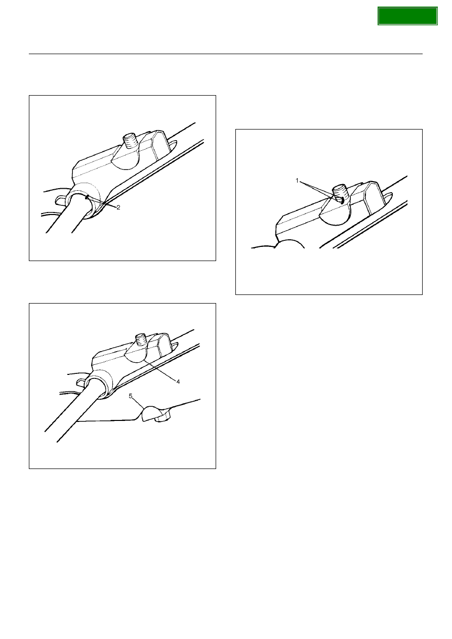
2. Apply grease to the portion that fits into the bracket 

then install height control arm and align the setting 
marks(2).

410RS005

3. Apply grease to the bolt portion of the end piece(4).  

Apply grease to the portion of the seat(5) that fits 
into the bracket.

410RS008

4. Apply grease to the serrated portions.

5. Install adjust bolt and seat, then turn the adjust bolt 

to the setting mark(1) applied during disassembly. 

NOTE:  Adjust the trim height. Refer to 

Front End 

Alignment Inspection and Adjustment in Steering 
section

.

410RS004

SECTION

FRONT SUSPENSION

3C–11

Knuckle

Knuckle and Associated Parts

410RW006

Legend

EndOFCallout

Removal

1. Raise the vehicle and support the frame with 

suitable safety stands.

2. Remove wheel and tire assembly. Refer to 

Wheel in 

this section

.

3. Remove the brake caliper. Refer to 

Disc Brakes in 

Brake section

.

4. Remove the hub assembly. Refer to 

Front Hub and 

Disk in this section

.

5. Remove tie–rod end from the knuckle. Refer to 

Power Steering Unit in Steering section

.

6. Remove the speed sensor from the knuckle.

7. Loosen torsion bar by height control arm adjust bolt, 

then remove torsion bar. Refer to 

Torsion Bar in this 

section

(1) Torsion Bar
(2) Lower Ball Joint, Nut and Cotter Pin
(3) Back Plate
(4) Knuckle Assembly
(5) Knuckle

(6) Needle Bearing
(7) Thrust Washer
(8) Oil Seal
(9) Upper Ball Joint, Nut and Cotter Pin

(10) Wheel Speed Sensor

SECTION

3C–12

FRONT SUSPENSION

8. Remove wheel speed sensor.

9. Remove back plate.

10. Remove lower ball joint by using remover 5–8840–

2005–0.

CAUTION:  Be careful not to damage the ball joint 
boot.

901RW271

11. Remove upper ball joint by using remover 5–8840–

2121–0.

CAUTION:  Be careful not to damage the ball joint 
boot.

901RW273

12. Remove knuckle assembly.

13. Remove oil seal.

14. Remove washer.

15. Remove needle bearing by using remover 5–8840–

2000–0 and sliding hammer 5–8840–0019–0.

901RW272

Inspection and Repair

Make necessary correction or parts replacement if 
wear, damage,  corrosion or any other abnormal 
condition are found through inspection.
Check the following parts:

• Knuckle

• Knuckle  arm

• Needle bearing

• Thrust washer

Installation

1. Apply appropriate amount of multipurpose type 

grease to the new bearing  (Approx. 5 g) and install 
needle bearing by using installer 5–8840–2128–0 
and grip 5–8840–0007–0.

901RW275

SECTION

FRONT SUSPENSION

3C–13

2. Apply multipurpose type grease to the thrust 

washer,  and install washer with chamfered side 
facing knuckle. 

3. Use a new oil seal, and apply multipurpose type 

grease to the area surrounded by the lip (approx. 2 
g). Then use installer 5–8840–2127–0 and grip 5–
8840–0007–0 to install oil seal.  After fitting the oil 
seal to the installer,  drive it to the knuckle using a 
hammer or bench press until the tool front face 
contacts with the thrust washer.

901RW274

4. Install knuckle assembly.

5. Install upper ball joint and tighten the nut to the 

specified torque,  with just enough additional torque 
to align cotter pin holes. Install new cotter pin.

Torque: 98N·m (10.0kg·m/72lbft)

6. Install lower ball joint and tighten the nut to the 

specified torque,  with just enough additional torque 
to align cotter pin holes. Install new cotter pin.

Torque: 147N·m (15.0kg·m/108 lbft)

7. Install back plate.

8. Install wheel speed sensor.

9. Install torsion bar, refer to 

Torsion Bar in this section

NOTE:  Adjust the trim height. Refer to 

Front End 

Alignment Inspection and Adjustment  in Steering

.

SECTION


Content   ..  1270  1271  1272  1273   ..