Opel Frontera UE. Manual - part 1271


  Index      Opel     Opel Frontera UE - service repair manual 1999-2001 year


Search            


Content   ..  1269  1270  1271  1272   ..


Opel Frontera UE. Manual - part 1271


3C–6

FRONT SUSPENSION

Shock Absorber

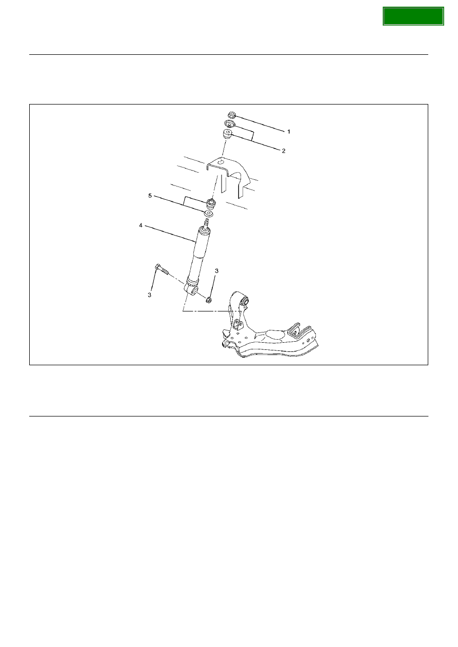
Shock Absorber and Associated Parts

450RW009

Legend

EndOFCallout

Removal

1. Raise the vehicle and support it with suitable safety 

stands.

2. Remove wheel and tire assembly. Refer to Wheel 

Replacement in this section.

3. Remove bolt and nut.

4. Remove nut.

5. Remove rubber bushing and washer.

6. Remove shock absorber.

7. Remove rubber bushing and washer.

Inspection and Repair

Make necessary correction or parts replacement if 
wear, damage,  corrosion or any other abnormal 
condition are found through inspection.
Check the following parts :

• Shock absorber

• Rubber  bushing

Installation

1. Install rubber bushing and washer.

2. Install shock absorber.

3. Install rubber bushing and washer.

4. Install nut, then tighten it to the specified torque.

Torque: 20N·m (2.0kg·m/14lbft)

5. Install bolt and nut, then tighten to the specified 

torque.

Torque: 93N·m (9.5kg·m/69lbft)

(1) Nut
(2) Rubber Bushing and Washer
(3) Bolt and Nut

(4) Shock Absorber
(5) Rubber Bushing and Washer

SECTION

FRONT SUSPENSION

3C–7

Stabilizer Bar

Stabilizer Bar and Associated Parts

410R100001

Legend

EndOFCallout

Removal

1. Raise the vehicle and support the frame with 

suitable safety stands.

2. Remove the stone guard.

3. Remove wheel and tire assembly. Refer to Wheel 

Replacement in this section.

4. Remove nut (4) and (6).

CAUTION:  Be careful not to break the ball joint 
boot. 

5. Remove link.

6. Remove bracket.

7. Remove stabilizer bar.

8. Remove rubber bushing.

Inspection and Repair

Make necessary correction or parts replacement if 
wear, damage,  corrosion or any other abnormal 
condition are found through inspection.
Check the following parts :

• Stabilizer bar

• Rubber bushing

• Link ball joint 

Installation

1. Install rubber bushing.

2. Install stabilizer bar.

3. Install bracket and bolt, then tighten it to the 

specified torque.

Torque: 25N·m (2.6kg·m/18lbft)

4. Install link.

5. Install nut (4), (6) and washer, then tighten it to the 

specified torque.

Torque: 50N·m (5.1kg·m/37lbft)

(1) Rubber Bushing
(2) Bracket and Bolt
(3) Link

(4) Nut
(5) Stabilizer Bar
(6) Nut and Washer

SECTION

3C–8

FRONT SUSPENSION

Torsion Bar

Torsion Bar and Associated Parts

410RS003

Legend

EndOFCallout

Removal

1. Raise the vehicle and support the frame with 

suitable safety stands.

2. Apply the setting marks(1) to the adjust bolt and end 

piece, then remove adjust bolt, end piece and seat.

410RS004

(1) Adjust Bolt, End Piece and Seat
(2) Height Control Arm

(3) Torsion Bar

SECTION

FRONT SUSPENSION

3C–9

3. Apply the setting marks(2) to the height control arm 

and torsion bar, then remove height control arm.

410RS005

4. Apply the setting marks(3) to the torsion bar and 

lower control arm, then remove torsion bar. 

410RS006

Inspection and Repair

Make necessary correction or parts replacement if 
wear, damage, corrosion or any other abnormal 
condition are found through inspection. 
Check the following parts:

• Torsion bar

• Height control arm

• Adjust bolt

• Rubber seat 

Installation

1. Apply grease to the serrated portions, then install 

torsion bar. Make sure the bars are on their correct 
respective sides and align the setting marks(3).

410RS007

410RS006

SECTION


Content   ..  1269  1270  1271  1272   ..