Opel Frontera UE. Manual - part 1166


  Index      Opel     Opel Frontera UE - service repair manual 1999-2001 year


Search            


Content   ..  1164  1165  1166  1167   ..


Opel Frontera UE. Manual - part 1166


SECURITY AND LOCKS

8H–7

Removal

1. Disconnect the battery ground cable.

2. Remove rear corner garnish.

3. Remove courtesy light lens.

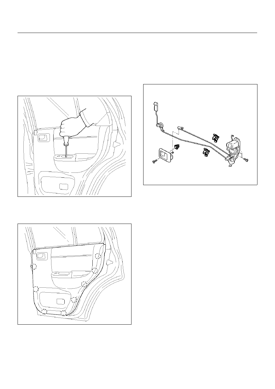
4. Remove the screw while pulling the inside lever 

toward you and then remove the inside handle.

5. Remove the two screws at the pull case and 

courtesy light.

655RW003

6. Pull out the trim panel at the eight clip positions.

• Disconnect the power window switch connector 

and courtesy light connector.

655RW002

7. Remove the bracket.

8. Remove the waterproof sheet.

• Taking notice of the door harness, peel the 

waterproof sheet off the door panel carefully.

9. Disconnect the locking links and remove the door 

lock assembly fixing screws to remove the door lock 
assembly.

652RW002

Installation

To install, follow the removal steps in the reverse order, 
noting the following points.

1. Apply chassis grease to the lock assembly and 

striker moving surface.

2. Tighten the door lock assembly fixing screws to the 

specified torque.

Torque 7 N·m (0.7kg·m/61lbin)

3. Check that the door lock operates smoothly.

8H–8

SECURITY AND LOCKS

Rear Outside Handle

Rear Outside Handle and Associated Parts

655RW012

Legend

EndOFCallout

Removal

1. Disconnect the battery ground cable.

2. Remove the door trim panel.

• Refer to Rear Door Lock Assembly in this section.

3. Remove the waterproof sheet.

• Taking notice of the door harness, peel the 

waterproof sheet off the door panel carefully.

4. Disconnect the locking link and remove fixing bolts 

to remove the outside handle.

Installation

To install, follow the removal steps in the reverse order, 
noting the following point:

1. Check that the outside handle operates smoothly.

2. Tighten the outside handle fixing bolts to the 

specified torque.

Torque 9 N·m (0.9kg·m/78lbin)

(1) Outside Handle
(2) Door Lock Assembly
(3) Bracket
(4) Rear Corner Garnish
(5) Door Trim Panel

(6) Courtesy Light Lens
(7) Power Window Switch
(8) Inside Handle
(9) Waterproof Sheet

SECURITY AND LOCKS

8H–9

Tailgate Lock and Hatchgate Lock (LWB)

Tailgate Lock, Hatchgate Lock and Associated Parts

681RW015

Legend

EndOFCallout

(1) Hatchgate Lock Assembly
(2) Tailgate Assembly
(3) Tailgate Lock Relay Lever
(4) Waterproof Sheet
(5) Trim Cover Assembly

(6) Key Cylinder
(7) Tailgate Lock Assembly
(8) Outside Handle
(9) Hatchgate Lock Actuator Assembly

8H–10

SECURITY AND LOCKS

Removal

1. Disconnect the battery ground cable.

2. Remove the tailgate trim cover assembly (3).

• Remove the two screws (2) holding the hatchgate 

lock assembly (1) first and the two screws fixing 
the trim cover assembly. Pull up the trim cover 
while detaching the clips from tailgate panel.

683RW001

3. Remove the tailgate trim brackets (2).

• Remove the three screws (3) and screw 

grommets (1).

4. Remove the waterproof sheet (4).

• Remove the waterproof sheet, taking special care 

so as not to break it.

681RW014

5. Remove the hatchgate lock.

• Disconnect the lock link and connector and 

remove the three fixing bolts.

6. Remove the key cylinder.

• Disconnect the lock links.

• Remove the key cylinder retaining clip with screw 

driver to remove the key cylinder.

683RW025

7. Remove the hatchgate lock actuator assembly.

• Disconnect the actuator harness connector.

• Remove the two nuts holding hatchgate lock 

actuator assembly from inside.

8. Remove the outside handle.

• Disconnect the lock links.

• Remove the two bolts holding the outside handle 

from inside.

9. Remove tailgate lock assembly.

• Remove the three screws holding the lock 

assembly.


Content   ..  1164  1165  1166  1167   ..