Opel Frontera UE. Manual - part 1167


  Index      Opel     Opel Frontera UE - service repair manual 1999-2001 year


Search            


Content   ..  1165  1166  1167  1168   ..


Opel Frontera UE. Manual - part 1167


SECURITY AND LOCKS

8H–11

Installation

To install, follow the removal steps in the reverse order, 
noting the following points:

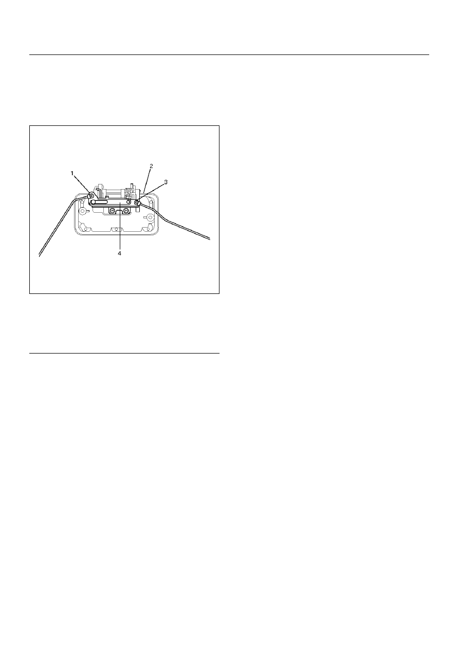
1. When setting up links, pay attention to the position 

and direction of the links.

683RW003

Legend

EndOFCallout

2. Apply chassis grease to the lock assembly and 

striker moving surface.

3. Check that the tailgate lock operates correctly after 

installing it.

4. Tighten the hatchhgate lock assembly fixing bolts to 

the specified torque.

Torque 9N·m (0.9kg·m/78lbin)

5. Tighten the tailgate lock assembly fixing screws to 

the specified torque.

Torque 7N·m (0.7kg·m/61lbin)

(1) Tailgate Lock Link
(2) Outside Handle
(3) Key Cylinder Link
(4) Cancel Mechanism

8H–12

SECURITY AND LOCKS

Tailgate Lock (SWB)

Tailgate Lock and Associated Parts

681RW013

Legend

EndOFCallout

Removal

1. Disconnect the battery ground cable.

2. Remove the tailgate glass assembly and tailgate 

glass stay.

• Refer to Tailgate Glass (SWB) in Body Structure 

section.

3. Remove the tailgate trim cover assembly.

• Remove the two screws fixing the trim cover 

assembly and pull up the trim cover after 
detaching the clips from tailgate panel.

4. Remove the tailgate trim brackets (2).

• Remove the three fixing screws (3) and screw 

grommets (1).

(1) Tailgate Assembly
(2) Waterproof sheet
(3) Trim Cover Assembly
(4) Key Cylinder

(5) Tailgate Lock Assembly
(6) Outside Handle
(7) Hatchgate Lock Actuator Assembly

SECURITY AND LOCKS

8H–13

5. Remove the waterproof sheet (4).

• Remove the waterproof sheet, taking special care 

so as not to break it.

681RW014

6. Remove the key cylinder.

• Disconnect the lock links.

• Remove the key cylinder retaining clip with screw 

driver to remove the key cylinder.

7. Remove the hatchgate lock actuator assembly.

• Disconnect the actuator harness connector.

• Remove the two nuts holding hatchgate lock 

actuator assembly from inside.

8. Remove the outside handle.

• Disconnect the lock link.

• Remove the two bolts holding the outside handle 

from inside.

9. Remove tailgate lock assembly.

• Remove the three screws holding the lock 

assembly.

Installation

To install, follow the removal steps in the reverse order, 
noting the following points:

1. Apply chassis grease to the lock assembly and 

striker moving surface.

2. Tighten the tailgate lock assembly fixing screws to 

the specified torque.

Torque 7 N·m (0.7kg·m/61lbin)

3. Check that the tailgate lock operates correctly after 

installing it.

8H–14

SECURITY AND LOCKS

Fuel Filler Door Lock

Fuel Filler Door Lock and Associated Parts

This illustration is based on the SWB model.

686RW014

Legend

EndOFCallout

Removal

1. Disconnect the battery ground cable.

2. Unlock the fuel filler door.

3. Remove the luggage trim cover on the left side.

• Remove the two clips, then canopy cover.

• Remove the luggage side lid assembly.

• Remove the luggage side upper cover.

• Remove the luggage side front cover.

• Remove the one fixing screw on the front upper 

side of the luggage trim cover.

• Remove the rear and floor trim cover.

• Disconnect the accessory socket connector.

4. Remove the quarter trim cover (LWB).

• Refer to Interior Trim Panel (LWB) in Exterior/

Interior section.

5. Remove the fuel filler door lock actuator assembly.

• Remove the two fixing bolts and one fixing nut. 

(For LWB, one bolt and two nuts.)

6. Remove the fixing clip of the link.

(1) Link (SWB only)
(2) Clip (SWB only)
(3) Fuel Filler Door Lock Actuator Assembly
(4) Rod
(5) Accessory Socket
(6) Luggage Trim Cover

(7) Rear End Floor Trim Cover
(8) Canopy Cover
(9) Luggage Side Lid Assembly

(10) Luggage Side Upper Cover
(11) Luggage Side Front Cover


Content   ..  1165  1166  1167  1168   ..