Opel Frontera UE. Manual - part 116


  Index      Opel     Opel Frontera UE - service repair manual 1999-2001 year


Search            


Content   ..  114  115  116  117   ..


Opel Frontera UE. Manual - part 116


5A–10

BRAKE CONTROL SYSTEM

System Components

Electronic Hydraulic Control Unit (EHCU), three Wheel 
Speed Sensors, Warning Light, and G-sensor.

Electronic Hydraulic Control Unit (EHCU)

The EHCU consists of ABS control circuits, fault 
detector, and a fail-safe.  It drives the hydraulic unit 
according to the signal from each sensor, cancelling 
ABS to return to normal braking when a malfunction has 
occurred in the ABS.
The EHCU has a self-diagnosing function which can 
indicate faulty circuits during diagnosis.
The EHCU is mounted on the engine compartment rear 
right side.  It consists of a Motor, Plunger Pump, 
Solenoid Valves.
Solenoid Valves: Reduces or holds the caliper fluid 
pressure for each front disc brake or both rear disc 
brakes according to the signal sent from the EHCU.
Reservoir: Temporarily holds the brake fluid that returns 
from the front and rear disc brake caliper so that 
pressure of front disc brake caliper can be reduced 
smoothly.
Plunger Pump: Feeds the brake fluid held in the 
reservoir to the master cylinder.
Motor: Drives the pump according to the signal from 
EHCU.
Check Valve: Controls the brake fluid flow.
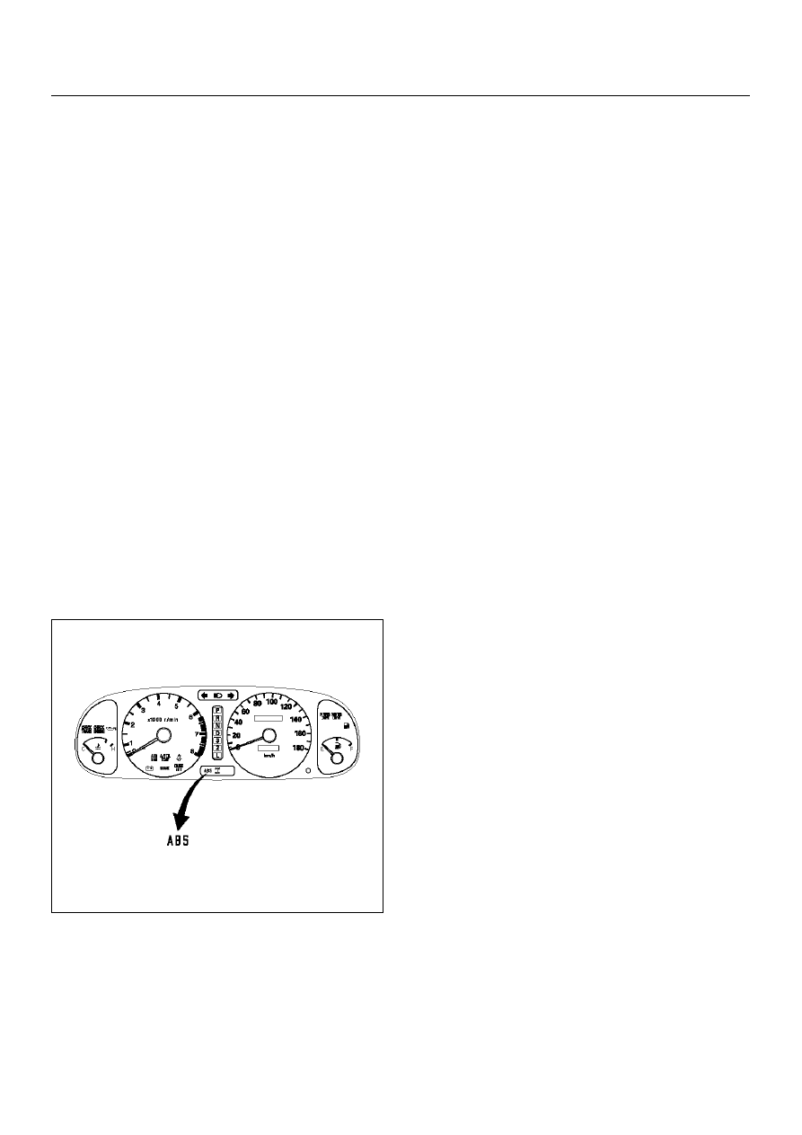
ABS Warning Light

825RX048

Vehicles equipped with the Anti-lock Brake System have 
an amber “ABS"  warning light in the instrument panel.  
The “ABS" warning light will illuminate if a malfunction  
in the Anti-lock Brake System is detected by the 
Electronic Hydraulic Control Unit (EHCU).   In case of 
an electronic malfunction, the EHCU will turn “ON" the 
“ABS" warning light  and disable the Anti-lock braking 
function.
The “ABS" light will turn “ON" for approximately three 

seconds after the ignition  switch is to the “ON" position.
If the “ABS" light stays “ON" after the ignition switch is 
the “ON" position,  or comes  “ON" and stays “ON" while 
driving, the Anti-lock Brake System should be inspected  
for a malfunction according to the diagnosis procedure.

Wheel Speed Sensor

It consists of a sensor and a rotor.   The sensor is 
attached to the knuckle on the front wheels and to the 
rear axle case on the rear differential.
The rotor is press-fit in the axle shaft.
The flux generated from electrodes magnetized by a 
magnet in the sensor varies due to rotation of the rotor,  
and the electromagnetic induction generates alternating 
voltage in the coil.   This voltage draws a “sine curve"  
with the frequency proportional to rotor speed and it 
allows detection of wheel speed.

G-Sensor

The G-sensor installed inside the EHCU detects the 
vehicle deceleration speed  and sends a signal to the 
EHCU.  In 4WD operation, all four wheels may  be 
decelerated in almost the same phase, since all wheels 
are connected mechanically.
This tendency is noticeable particularly on roads with 
low friction coefficient, and the ABS control is  adversely 
affected.
The G-sensor judges whether the friction coefficient of 
road surface is low or high, and  changes the EHCU's 
operating system to ensure ABS control.

Normal and Anti-lock Braking

Under normal driving conditions, the Anti-lock Brake 
System functions the same as a  standard power 
assisted brake system. However, with the detection of 
wheel lock-up,  a slight bump or kick-back will be felt in 
the brake pedal. This pedal “bump" will be followed by a 
series of short pedal pulsations which occurs in rapid 
succession.  The brake pedal pulsation will continue 
until there is no longer a need for the anti-lock function  
or until the vehicle is stopped. A slight ticking or popping 
noise may be heard during brake applications  when the 
Anti-lock features is being used.
When the Anti-lock feature is being used, the brake 
pedal may rise even as the brakes are being applied.  
This is also normal.  Maintaining a constant force on the 
pedal will provide the shortest stopping distance.

Brake Pedal Travel

Vehicles equipped with the Anti-lock Brake System may 
be stopped by applying normal force  to the brake pedal. 
Although there is no need to push the pedal beyond the 
point where it stops or holds the vehicle, by applying 
more force the pedal will continue to travel toward the 
floor.
This extra brake pedal travel is normal.

BRAKE CONTROL SYSTEM

5A–11

Acronyms and Abbreviations

Several acronyms and abbreviations are commonly 
used throughout this section:

ABS
Anti-lock Brake System

CIM
Coil Integrated Module

CKT
Circuit

DLC
Data Link Connector

EHCU
Electronic Hydraulic Control Unit

FL
Front Left

FR
Front Right

GEN
Generator

H/U
Hydraulic Unit

MV
Millivolts

RR
Rear

RPS
Revolution per Second

VDC
DC Volts

VAC
AC Volts

W/L
Warning Light

WSS
Wheel Speed Sensor

General Diagnosis

General Information

ABS troubles can be classified into two types, those 
which can be detected by the ABS warning light and 
those  which can be detected as a vehicle abnormality 
by the driver.
In either case, locate the fault in  accordance with the 
“BASIC DIAGNOSTIC FLOWCHART" and repair.
Please refer to Section 5C for the diagnosis of 
mechanical troubles such as brake noise, brake judder  
(brake pedal or vehicle vibration felt when braking), 
uneven braking, and parking brake trouble.

ABS Service Precautions

Required Tools and Items:

• Box  Wrench

• Brake  Fluid

• Special Tool
Some diagnosis procedures in this section require the 
installation of a special tool.

5-8840-0366-0 High Impedance Multimeter

When circuit measurements are requested, use a circuit 
tester with high impedance.

Computer System Service Precautions

The Anti-lock Brake System interfaces directly with the 
Electronic Hydraulic Control Unit  (EHCU) which is a 
control computer that is similar in some regards to the 
Powertrain Control Module.  These modules are 
designed to withstand normal current draws associated 
with vehicle operation.  However, care must be taken to 
avoid overloading any of the EHCU circuits. In testing for 
opens  or shorts, do not ground or apply voltage to any 
of the circuits unless instructed to do so by  the 
appropriate diagnostic procedure. These circuits should 
only be tested with a high impedance  multimeter 
5-8840-0366-0 or special tools as described in this 
section. Power should never be  removed or applied to 
any control module with the ignition in the “ON" position. 
Before removing or connecting battery cables, fuses or 
connectors, always turn the ignition switch to the “OFF" 
position.

General Service Precautions

The following are general precautions which should be 
observed when servicing and  diagnosing the Anti-lock 
Brake System and/or other vehicle systems. Failure to 
observe  these precautions may result in Anti-lock Brake 
System damage.

• If welding work is to be performed on the vehicle 

using an electric arc welder,  the EHCU and valve 
block connectors should be disconnected before the 
welding operation begins.

• The EHCU and valve block connectors should never 

be connected or disconnected with the ignition “ON" .

• If only rear wheels are rotated using jacks or drum 

tester, the system will diagnose a speed sensor 
malfunction and  the “ABS" warning light will 
illuminate. But actually no trouble exists. After 
inspection stop the engine once  and re-start it, then 
make sure that the “ABS" warning light does not 
illuminate.

If the battery has been discharged
The engine may stall if the battery has been completely 
discharged and the engine is started via jumper cables.  
This is because the Anti-lock Brake System (ABS) 
requires a large quantity of electricity.  In this case, wait 
until the battery  is recharged, or set the ABS to a 

5A–12

BRAKE CONTROL SYSTEM

non-operative state by removing the fuse for the ABS 
(60A). After the battery has been  recharged, stop the 
engine and install the ABS fuse. Start the engine again, 
and confirm that the ABS warning light does not light.

Note on Intermittents

As with virtually any electronic system, it is difficult to 
identify an intermittent failure. In such a case duplicating 
the system  malfunction during a test drive or a good 
description of vehicle behavior from the customer may 
be helpful in locating  a “most likely" failed component or 
circuit. The symptom diagnosis chart may also be useful 
in isolating the failure.  Most intermittent problems are 
caused by faulty electrical connections or wiring. When 
an intermittent failure is encountered,  check suspect 
circuits for:

• Suspected harness damage.

• Poor mating of connector halves or terminals not fully 

seated in the connector body (backed out).

• Improperly formed or damaged terminals.

Test Driving ABS Complaint Vehicles

In case that there has been an abnormality in the 
lighting  pattern of “ABS" warning light, the fault can be 
located in accordance with  the “DIAGNOSIS BY “ABS" 
WARNING LIGHT ILLUMINATION PATTERN" .  In case 
of such trouble as can be detected  by the driver as a 
vehicle symptom, however, it is necessary to give a test 
drive following the test procedure mentioned below,  
thereby reproducing the symptom for trouble diagnosis 
on a symptom basis:

1. Start the engine and make sure that the “ABS" W/L 

goes OFF.  If the W/L remains ON, it means that  the 
Diagnostic Trouble Code (DTC) is stored.  
Therefore, read the code and locate the fault.

NOTE:  The DTC cannot be cleared if the vehicle speed 
does not exceed 12 km/h (8 mph) at DTC, even though 
the repair operation is completed.

2. Start the vehicle and accelerate to about 30 km/h 

(19 mph) or more.

3. Slowly brake and stop the vehicle completely.

4. Then restart the vehicle and accelerate to about 40 

km/h (25 mph) or more.

5. Brake at a time so as to actuate the ABS and stop 

the vehicle.

6. Be cautious of abnormality during the test.  If the W/

L is actuated while driving, read the  DTC and locate 
the fault.

7. If the abnormality is not reproduced by the test, 

make best efforts to reproduce the situation 
reported by the customer.

8. If the abnormality has been detected, repair in 

accordance with the “SYMPTOM DIAGNOSIS" .

NOTE:

• Be sure to give a test drive on a wide, even road with 

a small traffic.

• If an abnormality is detected, be sure to suspend the 

test and start trouble diagnosis at once.

“ABS" Warning Light

When ABS trouble occurs to actuate “ABS" warning 
light, the trouble code corresponding to the trouble is  
stored in the EHCU.  Only ordinary brake is available 
with ABS being unactuated.  Even when “ABS" warning 
light is  actuated, if the starter switch is set ON after 
setting it OFF once, the EHCU checks up on the entire 
system and, if there  is no abnormality, judges ABS to 
work currently and the warning light is lit normally even 
though the trouble code is stored.

NOTE:  Illumination of the “ABS" warning light indicates 
that anti-lock braking is no longer available.  Power 
assisted braking without anti-lock control is still 
available.

Normal Operation

“ABS" Warning Light
When the ignition is first moved from “OFF" to “RUN" , 
the amber “ABS"  warning light will turn “ON" . The 
“ABS" warning light will turn “ON" during engine  
starting and will usually stay “ON" for approximately 
three seconds after the ignition switch is  returned to the 
“ON" position. The warning light should remain “OFF" at 
all other times.

BRAKE CONTROL SYSTEM

5A–13

Tech 2 Scan Tool

From 98 MY, Isuzu dealer service departments are 
recommended to use Tech 2. Please refer to  Tech 2 

scan tool user guide.

901RW257

Legend

EndOFCallout

(1) PCMCIA Card
(2) SAE 16/19 Adaptor
(3) DLC Cable

(4) Tech–2


Content   ..  114  115  116  117   ..