Opel Frontera UE. Manual - part 1010


  Index      Opel     Opel Frontera UE - service repair manual 1999-2001 year


Search            


Content   ..  1008  1009  1010  1011   ..


Opel Frontera UE. Manual - part 1010


7A–64

AUTOMATIC TRANSMISSION (4L30–E)

241RW009

241RS004

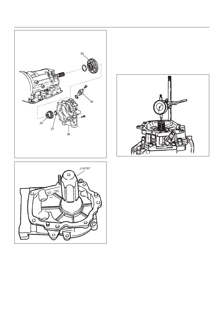
43. Main case end play measurement

1. Attach axial play checking tool on the extension

housing and set indicator to zero on output shaft.

2. Manually push output shaft upwards.

End play:  0.36mm – 0.80mm (0.014 in – 0.031in)

3. Remove axial play checking tool.

4. If end play is not correct, repeat selective washer

selection.

241RS005

44. Inspect servo piston seal ring.  Replace if necessary.

D

Ensure brake band is correctly positioned.  Rotate
output shaft if necessary.

D

Install J–38428 servo piston fitter in servo bore.

D

Install apply rod (40), round end toward band, return
spring (41) and piston assembly (42).

45. Install the J–23075 servo spring compressor with

offset to rear of case.

D

Compress servo piston seal ring, using fitter while
tightening the tool screw.

D

Install servo piston retaining ring (43).

D

Remove tool.

D

Adjust the brake band by tightening the servo
adjusting screw to 4.5 N·m torque.  Be certain the
lock nut is loose, then back-off the screw five turns
exactly. Hold piston sleeve with wrench and tighten
lock nut to 18.5 N·m torque. Be certain the adjusting
screw does not turn. 

7A–65

AUTOMATIC TRANSMISSION (4L30–E)

242RW004

46. Install two check balls (44).

244RW002

47. Inspect main case electrical connector and seal,

replace if necessary.

D

Install electrical 4 pin connector/main case and
wiring harness.

48. Install two J–25025–B guide pins into main case.

D

Install main case valve body complete assembly
(45) and manual valve link.

NOTE: Valve must be extended as the short end of
manual valve link is connected to the range selector lever.
Long end of link goes into valve.

D

Install seven 13 mm screws, tighten the specified
torque.

Torque: 20 N

m (15 lb ft)

D

Pass ground wire of adapter case wiring harness
assembly through the hole joining adapter fluid area
and main case fluid area.

D

Assemble 8.5 mm connector of ground wire under
the head of this valve body bolt and reinstall it.

D

Remove two guide pins.

244RW001

49. Install servo cover gasket, cover (46) and four 13 mm

screws.

Torque: 25 N

m (18 lb ft)

50. Connect wiring harness (47) to band control, shift

solenoids, and main case 4 pin connector.

51. Install manual detent roller and spring assembly (48)

with clip.

D

Install two 13 mm screws.

Torque: 20 N

m (15 lb ft)

52. Install oil filter (49) and three 13 mm screws.

Torque: 20 N

m (15 lb ft)

53. Install oil pan gasket, magnet, main oil pan (50),

sixteen 10 mm screws.

Torque: 11 N

m (96 lb in)

54. Inspect adapter case electrical connector and seal.

Replace if necessary.

D

Install electrical five pin connector and harness
assembly (52) in bottom of adapter case.

55. Install gasket, transfer plate, and gasket.

D

Install adapter case valve body (51) complete and
seven 13 mm screws.

Torque: 20 N

m (15 lb ft)

7A–66

AUTOMATIC TRANSMISSION (4L30–E)

56. Connect wiring harness harness assembly (52) to

converter clutch solenoid, force motor, and 5 pin
connector.

57. Install oil pan gasket, adapter case oil pan (53), and

twelve 10 mm screws.

Torque: 11 N

m (96 lb in)

D

Rotate transmission, with bottom pan facing down.

58. Install mode switch (54), two 10 mm screws, selector

lever nut, and cover.

10 mm screw

Torque: 13 N

m (113 lb in)

Nut

Torque: 23 N

m (17 lb ft)

D

Adjust using setting tool, refer to Mode Switch in
this section.

59. Install O-ring (55) on turbine shaft.

60. Install torque converter (56).

The converter assembly must be replaced under any
of the following conditions:

a. Evidence of damage to the pump assembly.
b. Metal particles are found after flushing the cooler

lines.

c. External leaks in hub weld area.
d. Converter pilot broken, damaged, or poor fit into

crankshaft.

e. Converter hub scored or damaged.
f. Internal failure in stator.
g. Contamination from engine coolant.
h. Excess end play.

D

Rotate transmission, bell housing up.  Spin
converter to insure proper fit.

61. Fill transmission through the overfill screw hole of oil

pan, using ATF DEXRON

–III. Refer to Changing

Transmission Fluid in this section.

241RW016

7A–67

AUTOMATIC TRANSMISSION (4L30–E)

Converter Housing and Oil Pump Assembly

Disassembled View

241RW003

Legend

(1) Converter Housing
(2) Outer Seal Ring
(3) Gasket

(4) Wear Plate
(5) Oil Pump Assembly
(6) Oil Seal Ring

Disassembly

1. Remove oil pump assembly from converter housing. 
2. Remove outer seal ring. 
3. Remove gasket. 
4. Remove wear plate. 
5. Remove oil seal ring.

Inspection and Repair

Visual Check:

If any damage, deformation, or local wear is found in a
converter housing, outer seal ring, wear plate, or oil seal
ring, replace it.

Reassembly

1. Install wear plate onto oil pump assembly.
2. Install converter housing onto complete oil pump

assembly. Align with two short J–38588 guide pins on
outer bolt holes.

D

Loosely install five 13mm bolts.

D

Center converter housing using J–38557 centering
tool.

D

Tighten five inner 13mm bolts in an alternating
pattern.

Torque: 20 N

m (15 lb ft)

241RW002

3. Install oil seal ring (3 screws).

Torque: 3 N

m (26 lb in)

4. Install gasket. 
5. Install outer seal ring. 


Content   ..  1008  1009  1010  1011   ..