Opel Frontera UE. Manual - part 1009


  Index      Opel     Opel Frontera UE - service repair manual 1999-2001 year


Search            


Content   ..  1007  1008  1009  1010   ..


Opel Frontera UE. Manual - part 1009


7A–60

AUTOMATIC TRANSMISSION (4L30–E)

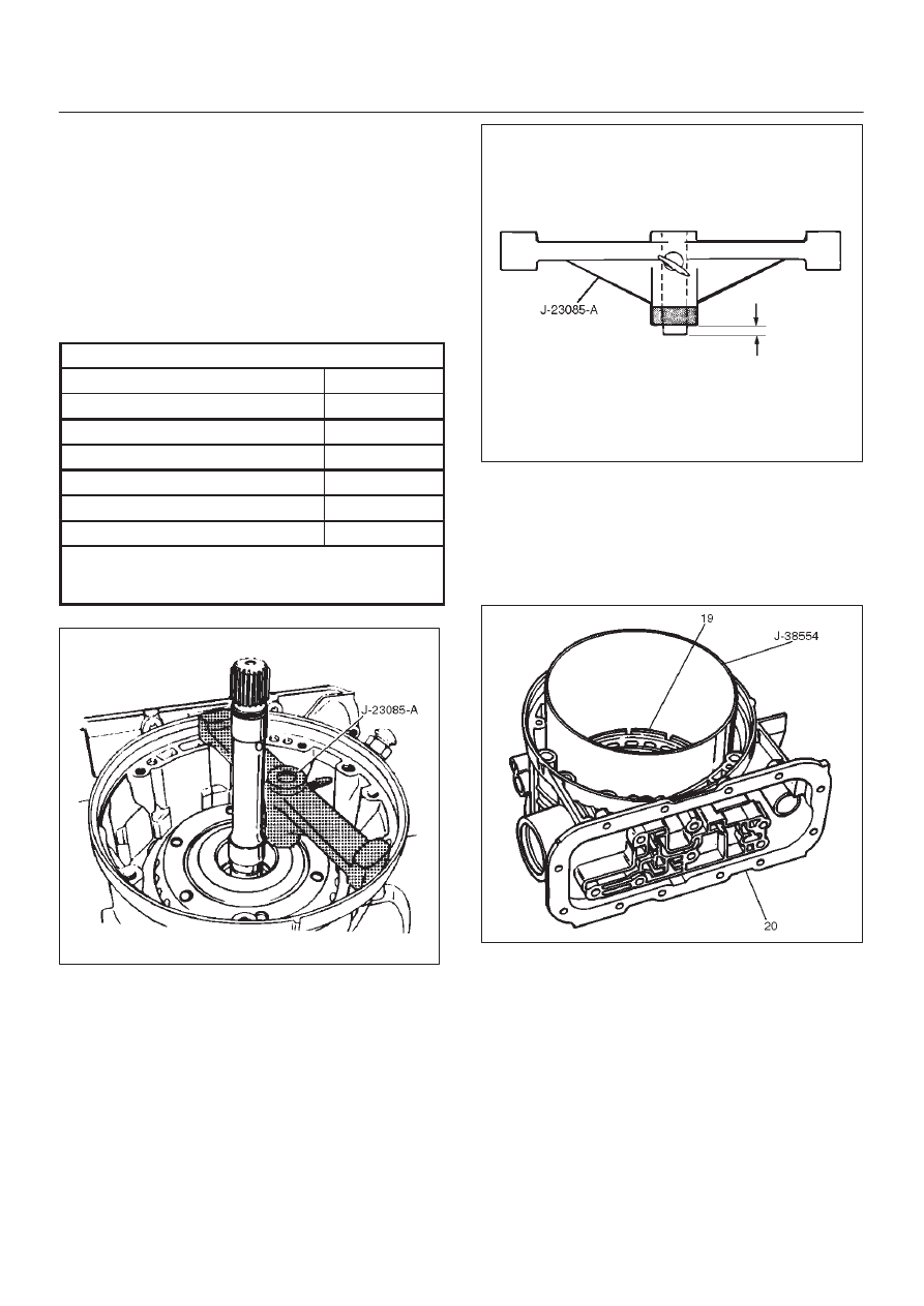
22. Second clutch end play measurement

1. Install the J–23085–A selective washer gauging

tool (with spacer ring) on the case flange and
against the intermediate shaft.

2. Position the inner shaft of the gauging tool against

the thrust surface of the second clutch hub.

3. Tighten thumb screw.  Remove the tool.

4. Fit the spacer ring on the inner shaft of the tool.

5. Measure the gap and select appropriate washer

as shown in the chart.

Selective Thrust Washer

Gap:  mm(in)

Color

1.53 – 1.63 (0.060 – 0.064)

Yellow

1.72 – 1.82 (0.068 – 0.072)

Red

1.91 – 2.01 (0.075 – 0.079)

Black

2.10 – 2.20 (0.083 – 0.087)

Natural

2.29 – 2.39 (0.090 – 0.094)

Green

2.48 – 2.58 (0.098 – 0.102)

Blue

FOLLOWING THE PROCEDURE SHOULD
RESULT IN FINAL END–PLAY FROM 0.36 mm TO
0.79 mm (0.014 in TO 0.031 in)

247RS003

247RS004

23. Inspect fourth clutch piston seals and replace if

necessary.

D

Lubricate J–38554 fourth clutch piston fitter and
install it on fourth clutch piston (19).

D

Install fourth clutch piston (19) in adapter case (20).

D

Remove fitter.

252RS003

24. Install retainer and spring assembly (22) into fourth

clutch piston (21).

25. Install snap ring (23) in adapter case.

D

Install J–23327 and J–23327–90 fourth clutch
spring compressor.

D

Seat snap ring in groove.

D

Remove compressor.

7A–61

AUTOMATIC TRANSMISSION (4L30–E)

252RW002

252RS004

26. Install selective washer using petroleum jelly.
27. Install two O-ring seals (24) in main case and adapter

case/main case seal ring (25).

28. Install J–38588 guide pins.

D

Install adapter case and center support assembly to
main case.

242RS004

29. Install thrust washer (26) into adapter case, with

tangs pointing downwards.

30. Preassemble overdrive internal gear (27) and thrust

bearing assembly (28) onto the turbine shaft and
overrun clutch assembly.

NOTE: Install  bearing assembly, black side up.  Use
petroleum jelly to keep assembly in place.

31. Install overdrive carrier (30) and internal gear

assembly into adapter case.

32. Install fourth clutch plates (29) in the following order:

Steel, Lined, Steel, Steel, Lined, Steel.  Steel plates
go in with short tang facing towards valve body
surface. 

33. Install fourth clutch retainer(31) with the notch facing

up and positioned towards valve body surface.

7A–62

AUTOMATIC TRANSMISSION (4L30–E)

252RW004

34. Overdrive clutch end play measurement

1. Install the J–23085–A selective washer gauging

tool on the adapter case flange and against the
input shaft.

2. Position the inner shaft of the tool against the

thrust surface of the overrun clutch housing.

3. Tighten thumb screw.  Remove the tool.

4. Measure gap.  Select appropriate size washer as

shown in the chart.

5. Set selective thrust washer aside.

Selective Thrust Washer

Gap:  mm(in)

Color

1.53 – 1.63 (0.060 – 0.064)

Yellow

1.72 – 1.82 (0.068 – 0.072)

Red

1.91 – 2.01 (0.075 – 0.079)

Black

2.10 – 2.20 (0.083 – 0.087)

Natural

2.29 – 2.39 (0.090 – 0.094)

Green

2.48 – 2.58 (0.098 – 0.102)

Blue

FOLLOWING THE PROCEDURE SHOULD
RESULT IN FINAL END–PLAY FROM 0.1 mm TO
0.8 mm (0.004 in TO 0.03 in)

252RS005

252RS006

35. Install selective washer (32).

NOTE: Use petroleum jelly to hold selective washer in
place.

36. Install gasket (33).
37. Install converter housing and oil pump assembly (34)

to adapter case.

D

Fit and tighten seven outer 13 mm screws.

Torque: 39 N

m (29 lb ft)

7A–63

AUTOMATIC TRANSMISSION (4L30–E)

D

Ensure free rotation of pump using J–23082–01
pump rotation tool.

241RW010

38. Overdrive clutch end play measurement

1. Fit J–25022 and J–24773–1 turbine shaft puller

on turbine shaft.

2. Position axial play checking tool on converter

housing mating face.

3. Pull turbine shaft upwards with puller until first

resistance is met. (due to weight of overdrive
assembly)

4. Maintain shaft in this position and set indicator to

zero.

5. Pull turbine shaft further upwards with puller.

Read end play shown on indicator.

End play:  0.1mm – 0.8mm (0.004 in – 0.031in)

6. Remove axial play checking tool and puller.

NOTE: If end play is not correct, repeat selective washer
selection.

252RW001

39. Inspect extension housing oil seal and replace if

necessary, using J–36797 extension housing oil seal
installer.

D

Rotate transmission to horizontal position, with
valve body side down.

D

Inspect parking wheel seal ring.  Replace if
necessary.

D

Install wheel parking lock assembly (35).

40. Install speed wheel (36) and snap ring (37).

NOTE: Use extra long, needle nose pliers.

41. Install gasket onto extension assembly with a thin

coating of oil.

D

Install extension housing assembly (38), and align
parking pawl shaft.

D

Install actuator assembly into extension assembly.

D

Install seven 8 mm hexagon socket head screws.

Torque: 32 N

m (24 lb ft)

42. Inspect speed sensor O-ring.  Replace if necessary.

D

Install speed sensor assembly (39) and 10 mm
screw.

Torque: 9 N

m (78 lb in)


Content   ..  1007  1008  1009  1010   ..