Opel Frontera UE. Manual - part 1008


  Index      Opel     Opel Frontera UE - service repair manual 1999-2001 year


Search            


Content   ..  1006  1007  1008  1009   ..


Opel Frontera UE. Manual - part 1008


7A–56

AUTOMATIC TRANSMISSION (4L30–E)

241RW004

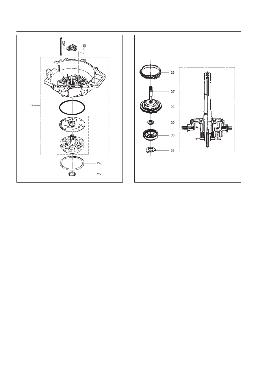
24. Remove fourth clutch retainer (26).
25. Grasp turbine shaft and lift out the overrun clutch

housing assembly (27) and fourth clutch plates (28).

26. Remove thrust bearing assembly (29).
27. Remove overdrive internal gear (30).
28. Remove thrust washer (31).

252RS001

29. Remove adapter case and center support assembly

(with fourth clutch piston) (32).

30. Remove seal ring (33).
31. Remove selective thrust washer (34) and two O-ring

seals (35) from main case.

32. Use J–23327 and J–23327–90 compressor to

compress the fourth clutch spring retainer and
springs (37).

D

Release snap ring (36) from groove.

D

Remove clutch compressor and snap ring (36).

33. Remove retainer and spring assembly (37).
34. Insert two converter housing/main case screws to

hold adapter case while pulling out fourth clutch
piston (38).

D

Remove fourth clutch piston assembly (38) from the
adapter case.

D

Remove converter housing/main case screws.

35. Grasp intermediate shaft, twist and pull out the

second and third clutch drum assemblies with reverse
clutch plates while holding onto output shaft (39).

7A–57

AUTOMATIC TRANSMISSION (4L30–E)

36. Separate second (40) and third clutch (41)

assemblies.

37. Remove thrust washer (42).
38. Remove reverse clutch plates (43 and 44) and

reverse clutch pressure plate (45).

39. Remove bearing (46) and washer (47).
40. Remove planetary carrier assembly (48).
41. Remove thrust bearing (49).
42. Remove reaction sun gear (50)
43. Remove needle bearing (51).
44. Remove brake drum (52).
45. Remove brake band (53).
46. Remove thrust bearing (54).

242RW005

47. Rotate case to horizontal position, valve body side

facing up.

D

Remove spring pin (55), using cutting pliers, then
remove parking lock and selector lever assembly
(56).

NOTE: Insert wire in the center of the spring pin to
prevent it from collapsing during removal.  Be aware of pin
height.  Protect machined face of main case.

48. Remove parking lock and range selector lever 17 mm

nut (57).

49. Remove parking lock and range selector lever (56),

and actuator assembly.

50. Remove selector shaft (58).

NOTE: Inspect the shaft for burrs before removing to
prevent damaging seal.  If necessary, remove burrs by
lightly sanding with an oilstone.

249RS004

Reassembly

1. Inspect selector shaft seal and replace it if necessary.

NOTE: Use a seal installer when replacing the seal.

D

Install selector shaft.

NOTE: Spring pin groove must be positioned inside the
case.

2. Install spring pin.  Be sure the selector shaft can move

freely.Do not push the pin flush with the case surface.
Leave enough height for removal.

3. Install actuator assembly (1).
4. Install parking lock and range selector lever (2) and

new 17 mm nut. Tighten the nut to the specified
torque.

Torque: 22 N

m (16 lb ft)

7A–58

AUTOMATIC TRANSMISSION (4L30–E)

249RS005

5. Rotate main case to vertical position, extension end

facing down.

D

Install brake band assembly (3).

NOTE: Be sure to align servo pin area with the servo hole.

6. Install thrust bearing (4).

NOTE: The case bushing acts as a guide for the thrust
bearing.

7. Install brake drum (5).
8. Install reaction sun gear (6).
9. Install needle bearing (7).

10. Inspect planetary carrier assembly (8) for wear and

damage. If necessary replace it.

D

Measure pinion end play clearance with a feeler
gauge.

Clearance: 0.13mm–0.89mm (0.005 in–0.035 in)

If clearance is outside specified value, replace the
planetary carrier assembly.

248RS001

11. Install the thrust bearing (9) on the output shaft.

NOTE: Use petroleum jelly to hold the thrust bearing in
place.

12. Align planetary pinions.  Each pinion is marked with

double points to indicate the master tooth space and
exactly opposite with a single point to indicate the
master tooth.  The markings on the planetary carrier
consist of double lines which are to be lined up with
the double points on two opposite pinions; the single
lines are to be lined up with the single points on the
other two pinions.

D

After all four pinions are lined up, slide on the third
clutch assembly. Rotate third clutch and check
mark alignment. Considering that the ring gear
tooth between the double points of one planetary
pinion is tooth number 1, count the teeth to check
that the single points on the two adjacent pinions
are between teeth 23 and 24 of the ring gear, and
that the ring gear tooth between the double points of
the opposite pinion is tooth number 46. If the ring
gear and pinions are not lined up, remove and
realign them.

13. Install planetary carrier (8) with third clutch (12).

NOTE: Do not force. When properly aligned, the parts will
fit together easily.

248RS002

14. Remove the third clutch  (12).
15. Install bearing (11) and washer (10).

7A–59

AUTOMATIC TRANSMISSION (4L30–E)

NOTE: Use  petroleum jelly to hold the washer and
bearing in place.

242RW002

16. Carefully align the second clutch plate inner tangs.

D

Install thrust washer, tangs pointing downward, and
locating tang positioned in slot on second clutch
hub.

NOTE: Use petroleum jelly to hold thrust washer in place.

17. Install third clutch and intermediate shaft assembly

(13) into the second clutch drum (14).

18. Install second and third clutch assemblies into the

main case.  Twist output shaft and clutch assemblies
to ensure proper fit.

247RS001

19. Install pressure plate (15) with lip side up, tang facing

valve body face.

20. Install reverse clutch plates. Start with a steel plate

(17) and alternate with a lined plate (16).

21. Install waved clutch plate (18) with center tang facing

valve body side.

247RS002


Content   ..  1006  1007  1008  1009   ..