Opel Frontera UE. Manual - part 96
 

  Index      Opel     Opel Frontera UE - service repair manual 1999-2001 year


Search            


Content   ..  94  95  96  97   ..


Opel Frontera UE. Manual - part 96


4C–18

DRIVE SHAFT SYSTEM

Actuator

Check and see that there is no damage, cracking, or 
other abnormality.
Functional Check

412RW021

412RW013

412RW007

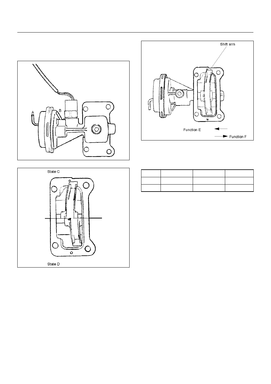
Disconnect the shift position switch and make sure of 
function with a vacuum of –400 mmHg applied to Ports 
A and B, in accordance with the table below.

If there is an abnormality, replace the actuator as an 
assembly.

NOTE:

1. If the actuator works under –400mmHg or less, 

there is no functional problem.

2. Be careful not to permit the entry of water or dust 

into the ports of the actuator.

Dimentional Check

Measure illustrated sizes 1, 2, and 3.

Limit

1=64.1mm (2.52in)

2=6.7 mm (0.26 in)

3=6.7 mm (0.26 in)

State

Port A

Port B

Function

C

–400 mmHg

A/P

E

D

A/P

–400 mmHg

F

DRIVE SHAFT SYSTEM

4C–19

412RS037

Reassembly

1. Install the new oil seal which has been immersed in 

differential gear oil, by using an oil seal installer 5–
8840–2407–0 and grip 5–8840–0007–0.

412RW034

2. Check the oil seal installation position (from shaft 

end to oil seal).

Depth:24.2 –25.2mm(0.95 –0.99in)

412RS052

3. Force a new needle bearing into inner shaft by using 

a Installer 5–8840–2408–0 and grip 5–8840–0007–
0.

412RS051

4C–20

DRIVE SHAFT SYSTEM

4. Place a new snap ring(internal) in inner shaft. 

Force a new inner shaft bearing into the inner shaft.

412RS044

5. Install snap ring(external).

NOTE:  Be careful not to damage the inner shaft.

6. Clean the housing contact surface of the front axle 

case and insert inner shaft assembly into the front 
axle case.

NOTE:  Be careful not to damage seal.

7. Install snap ring internal in the groove of front axle 

case.

NOTE:  Be sure to install the snap ring properly.

412RW017

8. Apply differential gear oil to clutch gear, then install 

clutch gear.

9. Apply differential gear oil to sleeve, then install 

sleeve.

10. Clean contact surface with the front axle and 

actuator mounting surface. Apply liquid gasket  to 
the contact surface on the front axle case, then 
install in the housing.

412RW023

11. Tighten bolts to specified torque.

Torque:75N·m(7.6kg·m/55 lbft)

12. Clean the actuator contact surface with the housing 

then Install and tighten shift position switch to 
specified torque.

Torque:39N·m (4.0kg·m/29 lbft)

13. Apply liquid gasket to the contact surface on the 

actuator side.

412RW012

DRIVE SHAFT SYSTEM

4C–21

14. Align shift arm with the groove of sleeve and install 

the actuator.

15. Tighten bolts to specified torque.

Torque:9N·m(0.9kg·m/78lbin)

16. Install front axle drive shaft and mounting bracket.  

Tighten fitting bolts to specified  torque.

Torque:116N·m (11.8kg·m/85lbft)

17. Pour specified amount of differential gear oil to filler 

plug.

Front Differential

Oil Capacity:1.4lit (1.48USqt)

Actuator Housing

Oil Capacity:0.12lit(0.13USqt)

18. Install filler plug through gasket and tighten to 

specified torque.

Torque:78N·m (8.0kg·m/58lbft)


Content   ..  94  95  96  97   ..