Opel Frontera UE. Manual - part 60
FRONT SUSPENSION
3C–19
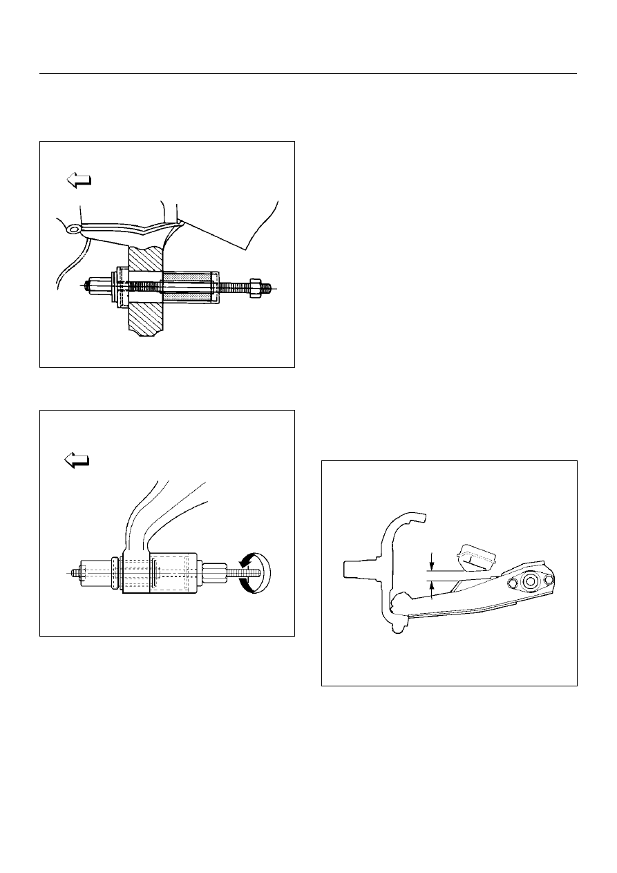
Installation
1. Install rear bushing by using installer 5–8840–2124–
0.
901RW053
2. Install front bushing by using installer 5–8840–
2123–0.
901RW156
3. Install lower ball joint bolt.
4. Install torsion bar arm bolt.
5. Install lower control arm.
6. Install rear bolt.
7. Install front bolt.
8. Install lower ball joint and tighten it to the specified
torque.
Torque: 116N·m (11.8kg·m/85lbft)
9. Install shock absorber and tighten it to the specified
torque.
Torque: 93N·m (9.5kg·m/69lbft)
10. Install stabilizer link and tighten it to the specified
torque.
Torque: 50N·m (5.1kg·m/37lbft)
11. Install torsion bar arm bracket and tighten it to the
specified torque.
Torque: 116N·m (11.8kg·m/85lbft)
12. Install Torsion bar, refer to Torsion Bar in this
section.
13. Install rear nut and tighten lower link nut finger–tight.
NOTE: Torque lower control arm nut after adjusting
buffer clearance.
Buffer clearance: 22mm (0.87in)
Torque: 235N·m (24.0kg·m/174lbft)
450RS012