Nissan Frontier D40. Manual - part 909


  Index      Nissan     Nissan Frontier D40 (2010 year) - Service and Repair Manual


Search            


Content   ..  907  908  909  910   ..


Nissan Frontier D40. Manual - part 909


PWC-18

< COMPONENT DIAGNOSIS >

POWER SUPPLY AND GROUND CIRCUIT

3.

 CHECK HARNESS CONTINUITY (REAR POWER WINDOW SWITCH RH)

1.

Turn ignition switch OFF.

2.

Disconnect main power window and door lock/unlock switch and
rear power window switch RH.
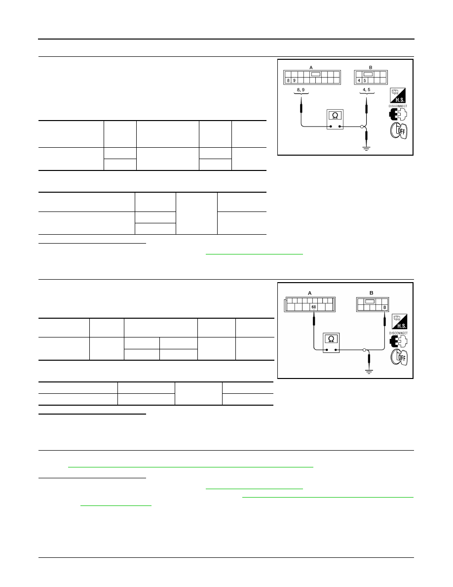
3.

Check continuity between main power window and door lock/
unlock switch connector (A) and rear power window switch RH
connector (B).

4.

Check continuity between main power window and door lock/unlock switch connector (A) and ground.

Is the inspection result normal?

YES

>> Check intermittent incident. Refer to 

GI-46, "Intermittent Incident"

.

NO

>> Repair or replace harness.

4.

 CHECK HARNESS CONTINUITY

1.

Disconnect BCM and rear power window switch.

2.

Check continuity between BCM connector (A) and rear power
window switch connector (B).

3.

Check continuity between BCM connector (A) and ground.

Is the inspection result normal?

YES

>> GO TO 5

NO

>> Repair or replace harness.

5.

 CHECK REAR POWER WINDOW SWITCH

Check rear power window switch.
Refer to 

PWC-18, "REAR POWER WINDOW SWITCH : Component Inspection"

.

Is the inspection result normal?

YES

>> Check intermittent incident. Refer to 

GI-46, "Intermittent Incident"

.

NO

>> Replace rear power window switch. Refer to 

PWC-67, "Removal and Installation - Rear Door

Switch (if equipped)"

.

REAR POWER WINDOW SWITCH : Component Inspection

INFOID:0000000005274619

COMPONENT INSPECTION

1.

 CHECK REAR POWER WINDOW SWITCH

Main power window 

and door lock/unlock 

switch connector

Terminal

Rear power window 

switch RH connec-

tor

Terminal

Continuity

D7 (A)

8

D303 (B)

4

Yes

9

5

Main power window and door 

lock/unlock switch connector

Terminal

Ground

Continuity

D7 (A)

8

No

9

LIIA2434E

BCM connector

Terminal

Rear power window 

switch connector

Terminal

Continuity

M20 (A)

68

LH

D203 (B)

8

Yes

RH

D303 (B)

BCM connector

Terminal

Ground

Continuity

M20 (A)

68

No

LIIA2175E

POWER SUPPLY AND GROUND CIRCUIT

PWC-19

< COMPONENT DIAGNOSIS >

C

D

E

F

G

H

I

J

L

M

A

B

PWC

N

O

P

Check rear power window switch.

Is the inspection result normal?

YES

>> Rear power window switch is OK.

NO

>> Replace rear power window switch. Refer to 

PWC-67, "Removal and Installation - Rear Door

Switch (if equipped)"

.

Rear power win-

dow switch LH or 

RH

Terminals

Condition

Continuity

6

5

DOWN

No

NEUTRAL or UP

Yes

8

NEUTRAL or UP

No

DOWN

Yes

7

4

UP

No

NEUTRAL or DOWN

Yes

8

NEUTRAL or DOWN

No

UP

Yes

LIIA2174E

PWC-20

< COMPONENT DIAGNOSIS >

POWER WINDOW MOTOR

POWER WINDOW MOTOR

DRIVER SIDE

DRIVER SIDE : Description

INFOID:0000000005274620

Door glass moves UP/DOWN by receiving the signal from power window main switch.

DRIVER SIDE : Component Function Check

INFOID:0000000005274621

1.

 CHECK POWER WINDOW MOTOR CIRCUIT

Does front power window motor LH operate when operating main power window and door lock/unlock switch?

Is the inspection result normal?

YES

>> Front power window motor LH is OK.

NO

>> Refer to 

PWC-20, "DRIVER SIDE : Diagnosis Procedure"

.

DRIVER SIDE : Diagnosis Procedure

INFOID:0000000005274622

Regarding Wiring Diagram information, refer to 

PWC-33, "Wiring Diagram"

.

1.

 CHECK MAIN POWER WINDOW AND DOOR LOCK/UNLOCK SWITCH OUTPUT SIGNAL

1.

Disconnect front power window motor LH.

2.

Turn ignition switch ON.

3.

Check voltage between front power window motor LH connector
and ground.

Is the measurement value within the specification?

YES

>> GO TO 2

NO

>> Replace main power window and door lock/unlock switch. Refer to 

PWC-65, "Removal and Instal-

lation"

.

2.

 CHECK HARNESS CONTINUITY

1.

Turn ignition switch OFF.

2.

Disconnect main power window and door lock/unlock switch.

3.

Check continuity between main power window and door lock/
unlock switch connector and front power window motor connec-
tor LH.

4.

Check continuity between main power window and door lock/unlock switch connector (A) and ground.

Terminal

Main power win-

dow and door lock/

unlock switch con-

dition

Voltage (V)

(Approx.)

(+)

(–)

Power window 

motor LH con-

nector

Terminal

D9

2

Ground

UP

Battery voltage

DOWN

0

1

UP

0

DOWN

Battery voltage

PIIB6431E

Main power window 

and door lock/unlock 

switch connector

Terminal

Front power win-

dow motor LH con-

nector

Terminal

Continuity

D7

6

D9

2

Yes

7

1

LIIA2056E

POWER WINDOW MOTOR

PWC-21

< COMPONENT DIAGNOSIS >

C

D

E

F

G

H

I

J

L

M

A

B

PWC

N

O

P

Is the inspection result normal?

YES

>> GO TO 3

NO

>> Repair or replace harness.

3.

 CHECK POWER WINDOW MOTOR

Check front power window motor LH.
Refer to 

PWC-21, "DRIVER SIDE : Component Inspection"

.

Is the inspection result normal?

YES

>> Check intermittent incident. Refer to 

GI-46, "Intermittent Incident"

.

NO

>> Replace power window motor LH. Refer to 

GW-16, "Front Door Glass Regulator"

.

DRIVER SIDE : Component Inspection

INFOID:0000000005274623

COMPONENT INSPECTION

1.

 CHECK FRONT POWER WINDOW MOTOR LH

Does motor operate by connecting the battery voltage directly to power window motor?

Is the inspection result normal?

YES

>> Front power window motor LH is OK.

NO

>> Replace front power window motor LH. Refer to 

GW-16, "Front Door Glass Regulator"

.

PASSENGER SIDE

PASSENGER SIDE : Description

INFOID:0000000005274624

Door glass moves UP/DOWN by receiving the signal from main power window and door lock/unlock switch or
power window and door lock/unlock switch RH.

PASSENGER SIDE : Component Function Check

INFOID:0000000005274625

1.

 CHECK POWER WINDOW MOTOR CIRCUIT

Does power window motor operate when operating main power window and door lock/unlock switch or power
window and door lock/unlock switch RH?

Is the inspection result normal?

YES

>> Front power window motor RH is OK.

NO

>> Refer to 

PWC-21, "PASSENGER SIDE : Diagnosis Procedure"

.

PASSENGER SIDE : Diagnosis Procedure

INFOID:0000000005274626

Regarding Wiring Diagram information, refer to 

PWC-33, "Wiring Diagram"

.

1.

 CHECK FRONT POWER WINDOW SWITCH RH OUTPUT SIGNAL

Main power window and door 

lock/unlock switch connector

Terminal

Ground

Continuity

D7

6

No

7

Terminal

Motor condition

(+)

(–)

1

2

DOWN

2

1

UP


Content   ..  907  908  909  910   ..