Nissan Frontier D40. Manual - part 829
OIL PUMP
LU-27
< ON-VEHICLE REPAIR >
[VQ40DE]
C
D
E
F
G
H
I
J
K
L
M
A
LU
N
P
O
OIL PUMP
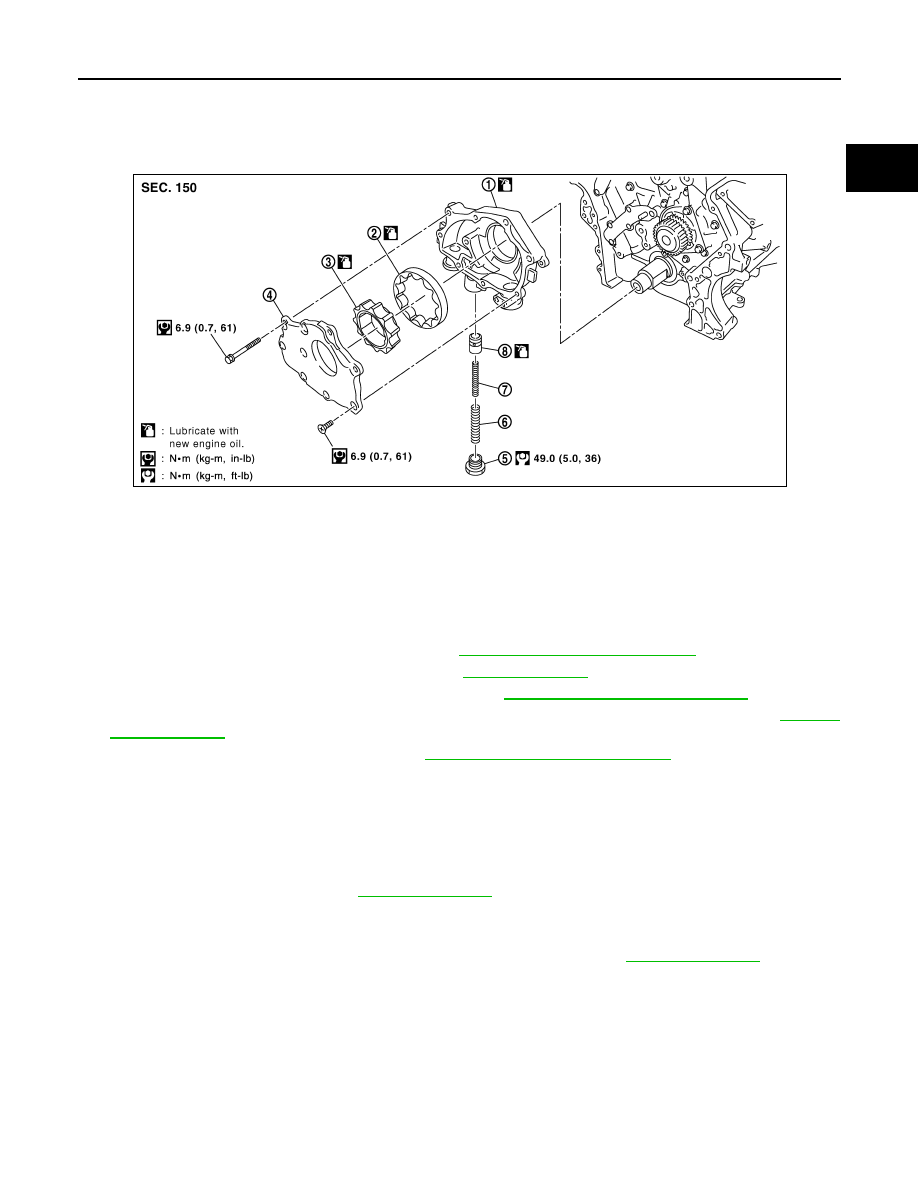
Exploded View
INFOID:0000000005272534
Removal and Installation
INFOID:0000000005272535
REMOVAL
1.
Disconnect the battery negative terminal. Refer to
PG-84, "Removal and Installation"
2.
Remove the RH and LH wheels and tires. Refer to
3.
Remove the RH and LH front fender protectors. Refer to
EXT-20, "Removal and Installation"
.
4.
Remove the air duct and resonator assembly and the air cleaner case (upper). Refer to
5.
Remove timing chain (primary) only. Refer to
EM-173, "Removal and Installation"
.
6.
Remove the oil pump assembly.
INSTALLATION
Installation is in the reverse order of removal, paying attention to the following.
• When installing, align crankshaft flat faces with inner rotor flat faces.
INSPECTION AFTER INSTALLATION
1.
Check the engine oil level. Refer to
2.
Start the engine and check for engine oil leaks.
3.
Stop engine and wait for 10 minutes.
4.
Check the engine oil level and adjust engine oil level as required. Refer to
1.
Oil pump body
2.
Oil pump outer rotor
3.
Oil pump inner rotor
4.
Oil pump cover
5.
Regulator valve plug
6.
Regulator valve spring
7.
Regulator valve spring
8.
Regulator valve
PBIC2826E