Nissan Frontier D40. Manual - part 798
INT-24
< ON-VEHICLE REPAIR >
HEADLINING
HEADLINING
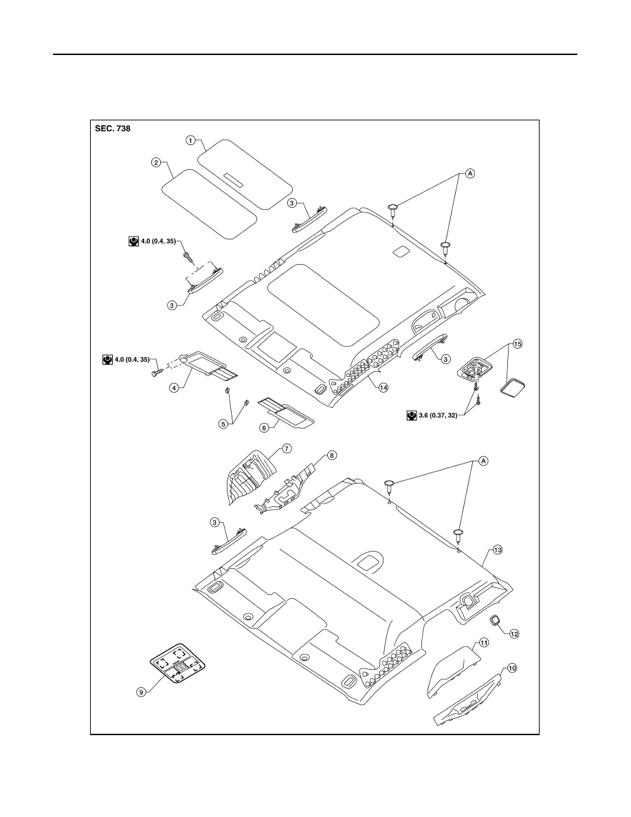
Removal and Installation
INFOID:0000000005274452
1.
Sunroof shade cover (if equipped)
2.
Sunroof welt (if equipped)
3.
Assist grip
4.
Sun visor assembly RH
5.
Sun visor holder RH/LH
6.
Sun visor assembly LH
AWJIA0163GB