Nissan Frontier D40. Manual - part 695


  Index      Nissan     Nissan Frontier D40 (2010 year) - Service and Repair Manual


Search            


Content   ..  693  694  695  696   ..


Nissan Frontier D40. Manual - part 695


GI-4

< HOW TO USE THIS MANUAL >

HOW TO USE THIS MANUAL

Relation between Illustrations and Descriptions

INFOID:0000000005589570

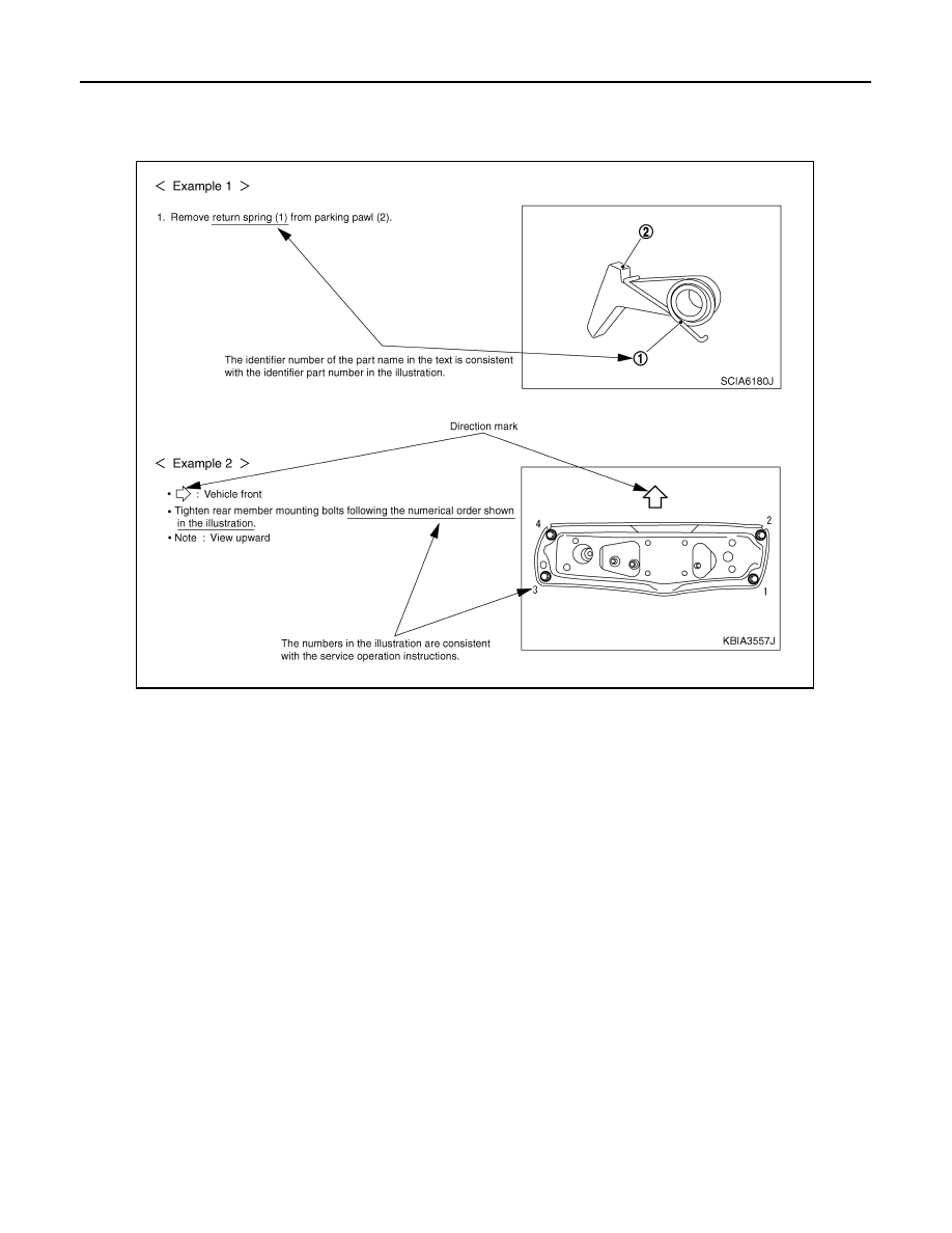
The following sample explains the relationship between the part description in an illustration, the part name in
the text and the service procedures.

Component

INFOID:0000000005272973

• THE LARGE ILLUSTRATIONS are exploded views (see the following) and contain tightening torques, lubri-

cation points, section number of the PARTS CATALOG (e.g. SEC. 440) and other information necessary to
perform repairs.
The illustrations should be used in reference to service matters only. When ordering parts, refer to the appro-
priate PARTS CATALOG.
Always check with the PARTS DEPARTMENT for the latest parts information.
Components shown in an illustration may be identified by a circled number. When this style of illustration is
used, the text description of the components will follow the illustration.

SAIA0519E

HOW TO USE THIS MANUAL

GI-5

< HOW TO USE THIS MANUAL >

C

D

E

F

G

H

I

J

K

L

M

B

GI

N

O

P

SYMBOLS

How to Read Wiring Diagram

INFOID:0000000005272975

CONNECTOR SYMBOLS 

Most of connector symbols in wiring diagrams are shown from the terminal side.

1.

Union bolt

2.

Copper washer

3.

Brake hose

4.

Cap

5.

Bleed valve

6.

Sliding pin bolt

7.

Piston seal

8.

Piston

9.

Piston boot

10.

Cylinder body

11.

Sliding pin

12.

Torque member mounting bolt

13.

Washer

14.

Sliding pin boot

15.

Bushing

16.

Torque member

17.

Inner shim cover

18.

Inner shim

19.

Inner pad

20.

Pad retainer

21.

Pad wear sensor

22.

Outer pad

23.

Outer shim

24.

Outer shim cover

1: PBC (Poly Butyl Cuprysil) grease 
or silicone-based grease

2: Rubber grease

: Brake fluid

Refer to GI section for additional symbol definitions.

SFIA2959E

SAIA0749E

GI-6

< HOW TO USE THIS MANUAL >

HOW TO USE THIS MANUAL

• Connector symbols shown from the terminal side are enclosed by

a single line and followed by the direction mark.

• Connector symbols shown from the harness side are enclosed by

a double line and followed by the direction mark.

• Certain systems and components, especially those related to

OBD, may use a new style slide-locking type harness connector.
For description and how to disconnect, refer to PG section,
“Description”, “HARNESS CONNECTOR”.

• Male and female terminals

Connector guides for male terminals are shown in black and
female terminals in white in wiring diagrams.

SAMPLE/WIRING DIAGRAM - EXAMPL - 

SAIA0257E

SGI363

HOW TO USE THIS MANUAL

GI-7

< HOW TO USE THIS MANUAL >

C

D

E

F

G

H

I

J

K

L

M

B

GI

N

O

P

• For detail, refer to following “DESCRIPTION”.

SGI091A


Content   ..  693  694  695  696   ..