Nissan Frontier D40. Manual - part 696
GI-8
< HOW TO USE THIS MANUAL >
HOW TO USE THIS MANUAL
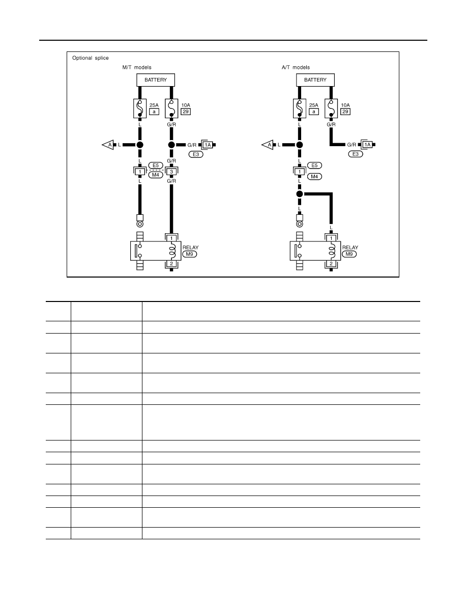
Optional Splice
DESCRIPTION
SGI942
Num-
ber
Item
Description
1
Power condition
• This shows the condition when the system receives battery positive voltage (can be operated).
2
Fusible link
• The double line shows that this is a fusible link.
• The open circle shows current flow in, and the shaded circle shows current flow out.
3
Fusible link/fuse loca-
tion
• This shows the location of the fusible link or fuse in the fusible link or fuse box. For arrange-
ment, refer to PG section, POWER SUPPLY ROUTING.
4
Fuse
• The single line shows that this is a fuse.
• The open circle shows current flow in, and the shaded circle shows current flow out.
5
Current rating
• This shows the current rating of the fusible link or fuse.
6
Connectors
• This shows that connector E3 is female and connector M1 is male.
• The G/R wire is located in the 1A terminal of both connectors.
• Terminal number with an alphabet (1A, 5B, etc.) indicates that the connector is SMJ connector.
Refer to PG section, SMJ (SUPER MULTIPLE JUNCTION).
7
Optional splice
• The open circle shows that the splice is optional depending on vehicle application.
8
Splice
• The shaded circle shows that the splice is always on the vehicle.
9
Page crossing
• This arrow shows that the circuit continues to an adjacent page.
• The A will match with the A on the preceding or next page.
10
Common connector
• The dotted lines between terminals show that these terminals are part of the same connector.
11
Option abbreviation
• This shows that the circuit is optional depending on vehicle application.
12
Relay
• This shows an internal representation of the relay. For details, refer to PG section, STAN-
DARDIZED RELAY.
13
Connectors
• This shows that the connector is connected to the body or a terminal with bolt or nut.