Nissan Frontier D40. Manual - part 614


  Index      Nissan     Nissan Frontier D40 (2010 year) - Service and Repair Manual


Search            


Content   ..  612  613  614  615   ..


Nissan Frontier D40. Manual - part 614


EM-188

< ON-VEHICLE REPAIR >

[VQ40DE]

CAMSHAFT

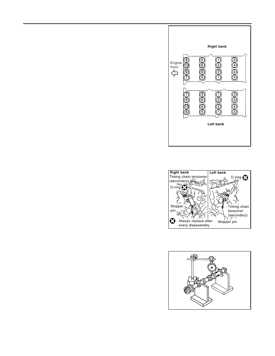
• Equally loosen camshaft bracket bolts in several steps in

reverse order as shown.

9.

Remove camshafts.

10. Remove valve lifters, if necessary.

• Identify installation positions, and store them without mixing them up.

11. Remove timing chain tensioner (secondary) from cylinder head.

• Remove timing chain tensioner (secondary) with its stopper

pin attached.

NOTE:
Stopper pin was attached when timing chain (secondary) was
removed.

INSPECTION AFTER REMOVAL

Camshaft Runout

1.

Put V-block on precise flat table, and support No. 2 and 4 journal
of camshaft.

CAUTION:

Do not support journal No. 1 (on the side of camshaft
sprocket) because it has a different diameter from the other
three locations.

2.

Set dial indicator vertically to No. 3 journal.

3.

Turn camshaft to one direction with hands, and measure the
camshaft runout on dial indicator. (Total indicator reading)

4.

If it exceeds the limit, replace camshaft.

Camshaft Cam Height

PBIC2050E

PBIC2111E

Standard

: Less than 0.02 mm (0.0008 in)

Limit

: 0.05 mm (0.0020 in)

PBIC0929E

CAMSHAFT

EM-189

< ON-VEHICLE REPAIR >

[VQ40DE]

C

D

E

F

G

H

I

J

K

L

M

A

EM

N

P

O

1.

Measure the camshaft cam height with micrometer.

2.

If wear exceeds the limit, replace camshaft.

Camshaft Journal Oil Clearance

CAMSHAFT JOURNAL DIAMETER

• Measure the outer diameter of camshaft journal with micrometer.

CAMSHAFT BRACKET INNER DIAMETER 

• Tighten camshaft bracket bolt with the specified torque. 
• Measure the inner diameter “A” of camshaft bracket with bore

gauge.

CAMSHAFT JOURNAL OIL CLEARANCE

• (Oil clearance) = (Camshaft bracket inner diameter) – (Camshaft journal diameter).

• If the calculated value exceeds the limit, replace either or both camshaft and cylinder head.

NOTE:
Camshaft bracket cannot be replaced as a single part, because it is machined together with cylinder head.
Replace whole cylinder head assembly.

Camshaft End Play

Standard:

Intake

: 45.465 - 45.655 mm (1.7900 - 1.7974 in)

Exhaust

: 45.075 - 45.265 mm (1.7746 - 1.7821 in)

Limit:

Intake

: 45.265 mm (1.7821 in)

Exhaust

: 44.875 mm (1.7667 in)

EMQ0072D

Standard:

No. 1

: 25.935 - 25.955 mm (1.0211 - 1.0218 in)

No. 2, 3, 4

: 23.445 - 23.465 mm (0.9230 - 0.9238 in)

PBIC0040E

Standard:

No. 1

: 26.000 - 26.021 mm (1.0236 - 1.0244 in)

No. 2, 3, 4

: 23.500 - 23.521 mm (0.9252 - 0.9260 in)

PBIC1645E

Standard:

No. 1

: 0.045 - 0.086 mm (0.0018 - 0.0034 in)

No. 2, 3, 4

: 0.035 - 0.076 mm (0.0014 - 0.0030 in)

Limit

: 0.15 mm (0.0059 in)

EM-190

< ON-VEHICLE REPAIR >

[VQ40DE]

CAMSHAFT

• Install dial indicator in thrust direction on front end of camshaft.

Measure the end play of dial indicator when camshaft is moved for-
ward/backward (in direction to axis).

• Measure the following parts if out of the limit.
- Dimension “A” for camshaft No. 1 journal

- Dimension “B” for cylinder head No. 1 journal bearing

• Following the standards above, replace camshaft and/or cylinder

head.

Camshaft Sprocket Runout

1.

Put V-block on precise flat table, and support No. 2 and 4 journal of camshaft.

CAUTION:

Do not support journal No. 1 (on the side of camshaft sprocket) because it has a different diameter
from the other three locations.

2.

Measure the camshaft sprocket runout with dial indicator. (Total
indicator reading)

• If it exceeds the limit, replace camshaft sprocket.

Valve Lifter 

Check if surface of valve lifter has any wear or cracks.
• If anything above is found, replace valve lifter. Refer to 

EM-242,

"Standard and Limit"

.

Valve Lifter Clearance

VALVE LIFTER OUTER DIAMETER

Standard

: 0.115 - 0.188 mm (0.0045 - 0.0074 in)

Limit

: 0.24 mm (0.0094 in)

SEM864E

Standard

: 27.500 - 27.548 mm (1.0827 - 1.0846 in)

Standard

: 27.360 - 27.385 mm (1.0772 - 1.0781 in)

KBIA2404J

Limit

: 0.15 mm (0.0059 in)

PBIC0930E

KBIA0182E

CAMSHAFT

EM-191

< ON-VEHICLE REPAIR >

[VQ40DE]

C

D

E

F

G

H

I

J

K

L

M

A

EM

N

P

O

• Measure the outer diameter at 1/2 height of valve lifter with

micrometer since valve lifter is in barrel shape.

VALVE LIFTER HOLE DIAMETER

• Measure the inner diameter of valve lifter hole of cylinder head with

inside micrometer.

VALVE LIFTER CLEARANCE

• (Valve lifter clearance) = (Valve lifter hole diameter) – (Valve lifter outer diameter), Refer to 

EM-132, "Valve

Clearance"

.

• If the calculated value is out of the standard, referring to each standard of valve lifter outer diameter and

valve lifter hole diameter, replace either or both valve lifter and cylinder head.

INSTALLATION

1.

Install timing chain tensioners (secondary) on both sides of cyl-
inder head.
• Install timing chain tensioner with its stopper pin attached. 
• Install timing chain tensioner with sliding part facing downward

on right-side cylinder head, and with sliding part facing upward
on left-side cylinder head.

• Install new O-rings as shown.

2.

Install valve lifters.
• Install it in the original position.

3.

Install camshafts.

Standard (Intake and exhaust)

: 33.977 - 33.987 mm (1.3377 - 1.3381 in)

JEM798G

Standard (Intake and exhaust)

: 34.000 - 34.016 mm (1.3386 - 1.3392 in)

SEM867E

Standard (Intake and exhaust)

: 0.013 - 0.039 mm (0.0005 - 0.0015 in)

PBIC2111E


Content   ..  612  613  614  615   ..