Nissan Frontier D40. Manual - part 613
EM-184
< ON-VEHICLE REPAIR >
[VQ40DE]
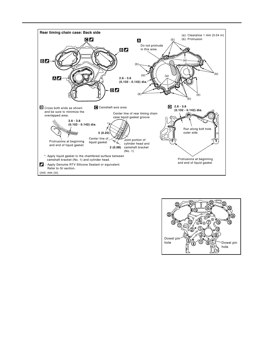
REAR TIMING CHAIN CASE
• Apply liquid gasket on installation position of water pump and cylinder head very completely.
d.
Align rear timing chain case with dowel pins (right and left) on cylinder block and install rear timing chain
case.
• Make sure O-rings stay in place during installation to cylinder block, cylinder head and camshaft bracket
(No. 1).
e.
Tighten bolts in numerical order as shown.
• There are two type of bolts with different torque specifications.
Refer to the following for installing bolts.
f.
After all bolts are tightened, retighten them to the specified torque in numerical order as shown.
• If liquid gasket protrudes, wipe it off immediately.
Bolt length
Bolt position
Torque specification
20 mm
(0.79 in)
1, 2, 3, 6, 7, 8,
9, 10
: 12.7 N·m (1.3 kg-m, 9 ft-lb)
16 mm
(0.63 in)
4, 5, 11
: 12.7 N·m (1.3 kg-m, 9 ft-lb)
16 mm
(0.63 in)
12 through 26
: 15.0 N·m (1.5 kg-m, 11 ft-lb)
PBIC2924E
PBIC2921E