Nissan Frontier D40. Manual - part 574


  Index      Nissan     Nissan Frontier D40 (2010 year) - Service and Repair Manual


Search            


Content   ..  572  573  574  575   ..


Nissan Frontier D40. Manual - part 574


EM-28

< ON-VEHICLE REPAIR >

[QR25DE]

INTAKE MANIFOLD

4.

Remove air cleaner case, air cleaner filter and air duct and resonator assembly. Refer to 

EM-25,

"Exploded View"

.

5.

Disconnect water hoses from electric throttle control actuator.

CAUTION:

• Perform this step when engine is cold.
• Do not spill engine coolant on drive belt.

6.

Remove mass air flow sensor from intake manifold.

CAUTION:

Handle the mass air flow sensor with care:
• Do not shock it.
• Do not disassemble it.
• Do not touch the internal sensor.

7.

Remove quick connector cap, and disconnect quick connector
at the engine side. Refer to 

EM-38

.

8.

Remove air duct. Refer to 

EM-25, "Exploded View"

.

9.

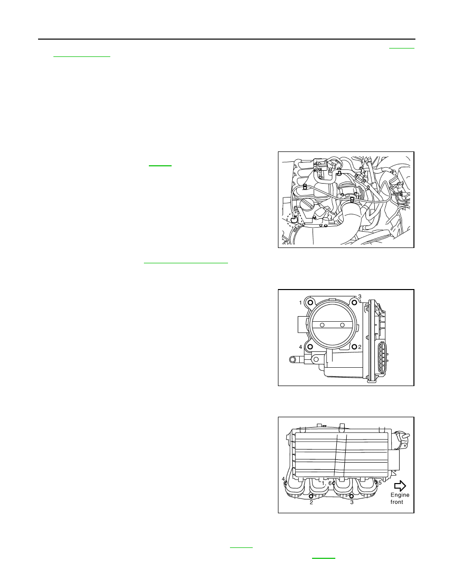
Remove electric throttle control actuator as follows:

a.

Disconnect harness connector.

b.

Loosen bolts in reverse order as shown, and remove electric
throttle control actuator and gasket. 

CAUTION:

• Handle carefully to avoid any shock to electric throttle

control actuator.

• Do not disassemble.

10. Disconnect harness, vacuum hoses and PCV hoses from intake manifold, and move them aside.

11. Remove intake manifold support.

12. Loosen nuts and bolts in reverse order as shown, and remove

intake manifold, fuel tube protector and gasket.

CAUTION:

• Cover engine openings to avoid entry of foreign materi-

als.

• Do not disassemble intake manifold.
NOTE:
Disregard No. 6 when loosening.

13. Remove EVAP canister purge volume control solenoid valve and vacuum hose adapter from intake mani-

fold, if necessary.

14. Disconnect sub-harness from fuel injector. Refer to 

EM-38

.

15. Remove fuel tube and fuel injector assembly from intake manifold. Refer to 

EM-38

.

LBIA0450E

PBIC2987E

PBIC2988E

INTAKE MANIFOLD

EM-29

< ON-VEHICLE REPAIR >

[QR25DE]

C

D

E

F

G

H

I

J

K

L

M

A

EM

N

P

O

INSTALLATION

Installation in the reverse order of removal.

Intake Manifold and Fuel Tube Protector

• If stud bolts were removed, install them and tighten to the specified torque below.

• Tighten in numerical order as shown.

NOTE:
No. 6 means double tightening of bolt No. 1.

Electric Throttle Control Actuator

• Tighten bolts equally and diagonally in several steps and in numer-

ical order as shown.

• Perform the “Throttle Valve Closed Position Learning” when har-

ness connector of electric throttle control actuator is disconnected.
Refer to 

EC-24, "Throttle Valve Closed Position Learning"

• Perform the “Idle Air Volume Learning” and “Throttle Valve Closed

Position Learning” when electric throttle control actuator is
replaced. Refer to 

EC-24, "Idle Air Volume Learning"

INSPECTION AFTER INSTALLATION

Make sure there are no fuel leaks at connections as follows:
1.

Apply fuel pressure to fuel lines by turning ignition switch ON (with the engine stopped). Then make sure
there are no fuel leaks at connections.

2.

Start the engine. With engine speed increased, make sure again there are no fuel leaks at connections.

WARNING:

Do not touch the engine immediately after stopped as the engine becomes extremely hot.
NOTE:
Use mirrors for checking on invisible points.

Intake manifold bolts

: 9.4 N·m (0.96 kg-m, 83 in-lb)

Use the following for locating bolts and nuts.

M8 x 38 mm (1.50 in) (Color green)

: No. 1, 6

M8 x 35 mm (1.38 in)

: No. 2, 3

Nut

: No. 4, 5

PBIC2988E

PBIC2987E

EM-30

< ON-VEHICLE REPAIR >

[QR25DE]

EXHAUST MANIFOLD AND THREE WAY CATALYST

EXHAUST MANIFOLD AND THREE WAY CATALYST

Exploded View

INFOID:0000000005274273

Removal and Installation

INFOID:0000000005274274

REMOVAL

1.

Disconnect harness connector of air fuel ratio sensor 1, and harness from bracket and middle clamp.

2.

Remove air fuel ratio sensor 1 using Tool.

CAUTION:

• Be careful not to damage air fuel ratio sensor 1.
• Discard any air fuel ratio sensor 1 which has been dropped from a height of more than 0.5 m

(19.7 in) onto a hard surface such as a concrete floor; replace with a new one.

3.

Remove exhaust front tube. Refer to 

EX-5, "Exploded View"

.

4.

Remove exhaust manifold cover.

5.

Remove bracket between exhaust manifold–three way catalyst assembly and transmission assembly.

1.

Air fuel ratio sensor 1

2.

Exhaust manifold and three way catalyst assembly 3.

Gasket

4.

Bracket

5.

Exhaust manifold cover

WBIA0647E

Tool number

:

 (J-44626)

EXHAUST MANIFOLD AND THREE WAY CATALYST

EM-31

< ON-VEHICLE REPAIR >

[QR25DE]

C

D

E

F

G

H

I

J

K

L

M

A

EM

N

P

O

6.

Loosen nuts in reverse order as shown to remove exhaust man-
ifold and three way catalyst assembly.

7.

Remove gasket.

CAUTION:

Cover engine openings to avoid entry of foreign materials.

INSPECTION AFTER REMOVAL

Surface Distortion

• Check the surface distortion of exhaust manifold and three way

catalyst assembly mating surface with straightedge and feeler
gauge.

• If it exceeds the limit, replace exhaust manifold and three way cat-

alyst assembly.

INSTALLATION

installation is in the reverse order of removal.

Exhaust Manifold

1.

If stud bolts were removed, install them and tighten to the specified torque.

2.

Tighten nuts in numerical order as shown.

3.

Tighten nuts in numerical order as shown again.

Air Fuel Ratio Sensor 1

CAUTION:

• Do not over tighten air fuel ratio sensor 1. Doing so may cause damage to air fuel ratio sensor 1,

resulting in the “MIL” coming on.

• Before installing new air fuel ratio sensor 1, clean exhaust system threads using suitable tool and

apply anti-seize lubricant.

PBIC2990E

Limit

: 0.3 mm (0.012 in)

PBIC2991E

Exhaust manifold stud bolt

: 14.7 N·m (1.5 kg-m, 11 ft-lb)

PBIC2990E

Oxygen sensor thread cleaner

:   —   (J-43897-12)

Oxygen sensor thread cleaner

:   —   (J-43897-18)


Content   ..  572  573  574  575   ..