Nissan Frontier D40. Manual - part 414


  Index      Nissan     Nissan Frontier D40 (2010 year) - Service and Repair Manual


Search            


Content   ..  412  413  414  415   ..


Nissan Frontier D40. Manual - part 414


P2119 ELECTRIC THROTTLE CONTROL ACTUATOR

EC-347

< COMPONENT DIAGNOSIS >

[QR25DE]

C

D

E

F

G

H

I

J

K

L

M

A

EC

N

P

O

 With CONSULT-III

1.

Turn ignition switch ON and wait at least 1 second.

2.

Set shift lever to D position (A/T) or 1st position (M/T) and wait at least 3 seconds.

3.

Set shift lever to N, P position (A/T) or Neutral (M/T) position.

4.

Start engine and let it idle for 3 seconds.

5.

Check DTC.

6.

If DTC is detected, go to 

EC-347, "Diagnosis Procedure"

.

 With GST

Follow the procedure “With CONSULT-III” above.

Diagnosis Procedure

INFOID:0000000005273383

1.

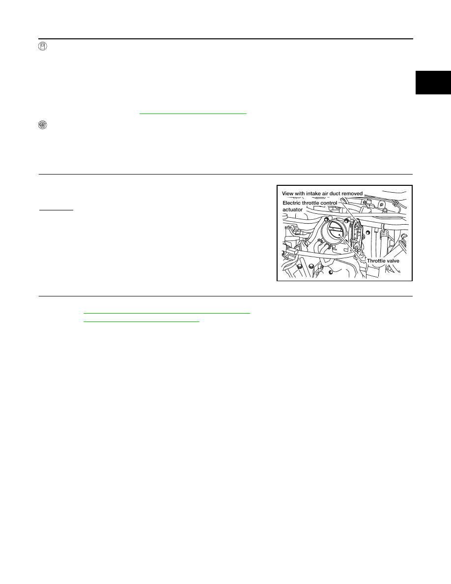
CHECK ELECTRIC THROTTLE CONTROL ACTUATOR VISUALLY

1.

Remove the intake air duct.

2.

Check if a foreign matter is caught between the throttle valve
and the housing.

OK or NG

OK

>> GO TO 2.

NG

>> Remove the foreign matter and clean the electric throttle

control actuator inside.

2.

REPLACE ELECTRIC THROTTLE CONTROL ACTUATOR

1.

Replace the electric throttle control actuator.

2.

Perform 

EC-24, "Throttle Valve Closed Position Learning"

.

3.

Perform 

EC-24, "Idle Air Volume Learning"

.

>> INSPECTION END

BBIA0623E

EC-348

< COMPONENT DIAGNOSIS >

[QR25DE]

P2122, P2123 APP SENSOR

P2122, P2123 APP SENSOR

Component Description

INFOID:0000000005273384

The accelerator pedal position sensor is installed on the upper end
of the accelerator pedal assembly. The sensor detects the accelera-
tor position and sends a signal to the ECM.
Accelerator pedal position sensor has two sensors. These sensors
are a kind of potentiometers which transform the accelerator pedal
position into output voltage, and emit the voltage signal to the ECM.
In addition, these sensors detect the opening and closing speed of
the accelerator pedal and feed the voltage signals to the ECM. The
ECM judges the current opening angle of the accelerator pedal from
these signals and controls the throttle control motor based on these
signals.
Idle position of the accelerator pedal is determined by the ECM
receiving the signal from the accelerator pedal position sensor. The ECM uses this signal for the engine oper-
ation such as fuel cut.

On Board Diagnosis Logic

INFOID:0000000005273385

These self-diagnoses have the one trip detection logic.
NOTE:
If DTC P2122 or P2123 is displayed with DTC P0643, first perform the trouble diagnosis for DTC P0643.
Refer to 

EC-285

.

FAIL-SAFE MODE

When the malfunction is detected, the ECM enters fail-safe mode and the MIL lights up.

DTC Confirmation Procedure

INFOID:0000000005273386

NOTE:
If DTC Confirmation Procedure has been previously conducted, always turn ignition switch OFF and wait at
least 10 seconds before conducting the next test.
TESTING CONDITION:
Before performing the following procedure, confirm that battery voltage is more than 8V at idle.

 WITH CONSULT-III

1.

Start engine and let it idle for 1 second.

2.

Check DTC.

3.

If DTC is detected, go to 

EC-349, "Diagnosis Procedure"

.

 WITH GST

Follow the procedure “WITH CONSULT-III” above.

PBIB1741E

DTC No.

Trouble diagnosis name

DTC detecting condition

Possible cause

P2122
2122

Accelerator pedal position 
sensor 1 circuit low input

An excessively low voltage from the APP 
sensor 1 is sent to ECM.

• Harness or connectors

(The APP sensor 1 circuit is open or 
shorted.)

• Accelerator pedal position sensor

(Accelerator pedal position sensor 1)

P2123
2123

Accelerator pedal position 
sensor 1 circuit high input

An excessively high voltage from the APP 
sensor 1 is sent to ECM.

Engine operating condition in fail-safe mode

The ECM controls the electric throttle control actuator in regulating the throttle opening in order for the idle position to be within +10 
degrees.
The ECM regulates the opening speed of the throttle valve to be slower than the normal condition.
So, the acceleration will be poor. 

P2122, P2123 APP SENSOR

EC-349

< COMPONENT DIAGNOSIS >

[QR25DE]

C

D

E

F

G

H

I

J

K

L

M

A

EC

N

P

O

Diagnosis Procedure

INFOID:0000000005273387

1.

CHECK GROUND CONNECTIONS

1.

Turn ignition switch OFF.

2.

Loosen and retighten two ground screws on the body. Refer to 

EC-90, "Ground Inspection"

.

OK or NG

OK

>> GO TO 2.

NG

>> Repair or replace ground connections.

2.

CHECK APP SENSOR 1 POWER SUPPLY CIRCUIT

1.

Disconnect accelerator pedal position (APP) sensor harness
connector.

2.

Turn ignition switch ON.

3.

Check voltage between APP sensor terminal 2 and ground with
CONSULT-III or tester.

OK or NG

OK

>> GO TO 3.

NG

>> Repair open circuit, short to ground or short to power in

harness or connectors.

3.

CHECK APP SENSOR 1 GROUND CIRCUIT FOR OPEN AND SHORT

1.

Turn ignition switch OFF.

2.

Disconnect ECM harness connector.

3.

Check harness continuity between APP sensor terminal 4 and ECM terminal 82.
Refer to Wiring Diagram.

4.

Also check harness for short to ground and short to power.

OK or NG

OK

>> GO TO 4.

NG

>> Repair open circuit, short to ground or short to power in harness or connectors.

4.

CHECK APP SENSOR 1 INPUT SIGNAL CIRCUIT FOR OPEN AND SHORT

BBIA0614E

BBIA0592E

Voltage: Approximately 5V

PBIB2608E

Continuity should exist.

EC-350

< COMPONENT DIAGNOSIS >

[QR25DE]

P2122, P2123 APP SENSOR

1.

Check harness continuity between ECM terminal 106 and APP sensor terminal 3.
Refer to Wiring Diagram.

2.

Also check harness for short to ground and short to power.

OK or NG

OK

>> GO TO 5.

NG

>> Repair open circuit, short to ground or short to power in harness or connectors.

5.

CHECK APP SENSOR

Refer to 

EC-350, "Component Inspection"

.

OK or NG

OK

>> GO TO 7.

NG

>> GO TO 6.

6.

REPLACE ACCELERATOR PEDAL ASSEMBLY

1.

Replace accelerator pedal assembly.

2.

Perform 

EC-24, "Accelerator Pedal Released Position Learning"

.

3.

Perform 

EC-24, "Throttle Valve Closed Position Learning"

.

4.

Perform 

EC-24, "Idle Air Volume Learning"

.

>> INSPECTION END

7.

CHECK INTERMITTENT INCIDENT

Refer to

GI-46, "Intermittent Incident"

 .

>> INSPECTION END

Component Inspection

INFOID:0000000005273388

ACCELERATOR PEDAL POSITION SENSOR

1.

Reconnect all harness connectors disconnected.

2.

Turn ignition switch ON.

3.

Check voltage between ECM terminals 106 (APP sensor 1 sig-
nal), 98 (APP sensor 2 signal) and ground under the following
conditions.

4.

If NG, replace accelerator pedal assembly and go to the next step.

5.

Perform 

EC-24, "Accelerator Pedal Released Position Learning"

.

6.

Perform 

EC-24, "Throttle Valve Closed Position Learning"

.

7.

Perform 

EC-24, "Idle Air Volume Learning"

.

Continuity should exist.

Terminal

Accelerator pedal

Voltage

106
(Accelerator pedal position 
sensor 1)

Fully released

 0.6 - 0.95V

Fully depressed

Less than 4.75V

98
(Accelerator pedal position 
sensor 2)

Fully released

0.3 - 0.45V

Fully depressed

Less than 2.4V

MBIB0023E


Content   ..  412  413  414  415   ..